Anchoring device

Inactive Publication Date: 2006-11-30
PLANTE DANIEL
View PDF9 Cites 4 Cited by
  • Summary
  • Abstract
  • Description
  • Claims
  • Application Information

AI Technical Summary

Benefits of technology

[0027] In addition, the flange, in its stabilizing configuration, reduces the risks of leakage passing around the anchoring member that could loosen the ground material therearound.
[0028] The proposed anchoring device also allows for the compaction of the loosened ground material along a significant portion of the shank inserted into the ground material hence increasing the overall lateral stability of the anchoring device.
[0029] Also, the proposed anchoring device is designed so as to be easily inserted into the ground material in a relatively stable configuration through a set of relatively quick and ergonomical steps without requiring special tooling, manual dexterity or excessive force. In particular, the flange thereof may be selectively moved between its auger blade and stabilizing plate configurations by merely rotating the anchoring device in selected directions relative to its longitudinal axis.

Problems solved by technology

One of the drawbacks associated with some prior art anchoring devices relates to the relative difficulty with which they can be inserted into the ground.
This tends to make the stake or shaft of the anchoring device less stable.
Particularly, the anchor shaft or stake may be able to move back and forth laterally and to loosen ground material and thereby loosen the anchoring device such that the latter becomes relatively ineffective.
Some prior art devices already inherently suffer from being relatively unstable as they tend to shift or lean to a non-vertical alignment when even moderate lateral forces are placed against thereagainst.
The problem of instability of anchoring devices is compounded, in certain regions, wherein anchoring devices are used in ground material subject to being frozen.
Prior art devices using compactor plates and / or stabilizing caps however suffer from numerous drawbacks.
Indeed, compactor plates such as disclosed in the hereinabove-mentioned patent create a relatively large obstructing surface which creates a significant drag force.
This drag force, in turn, makes insertion of the anchoring device into the ground material rather difficult.
Furthermore, the compactor plate only allows for compaction of material about a limited area adjacent the shank.
Also, in some situations, the interference it creates when protruding from the ground simply cannot be tolerated.

Method used


Image

  • Anchoring device
  • Anchoring device
  • Anchoring device

Examples


Embodiment Construction

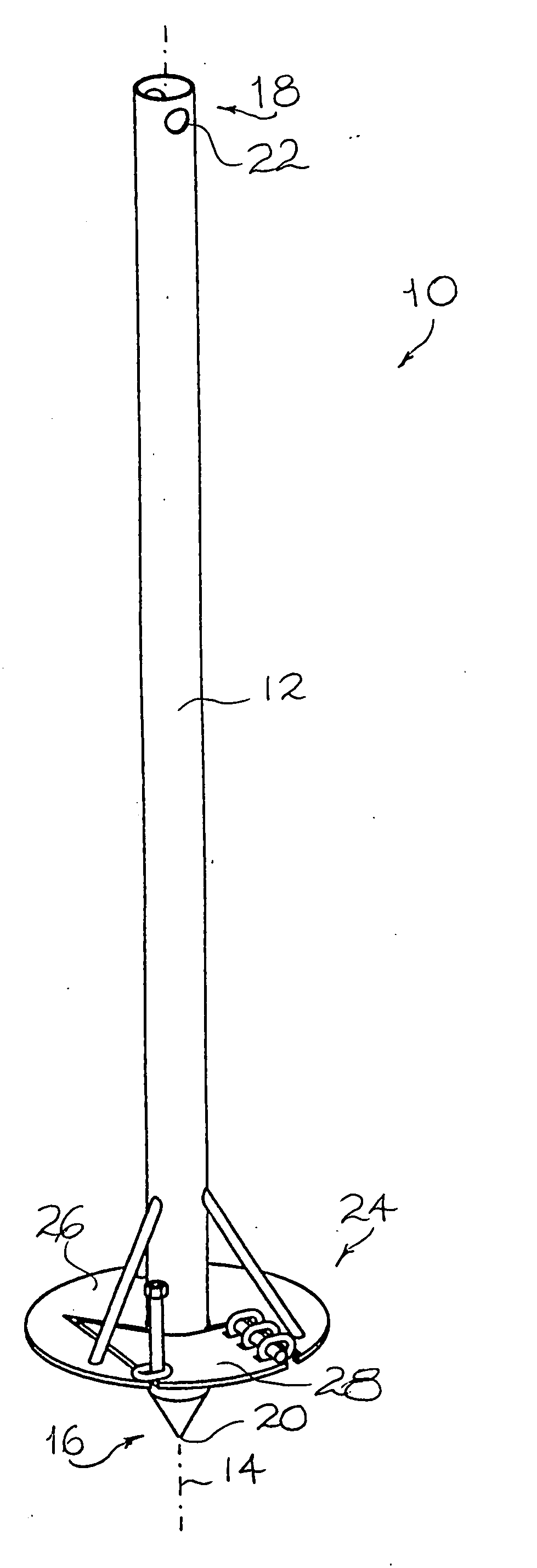
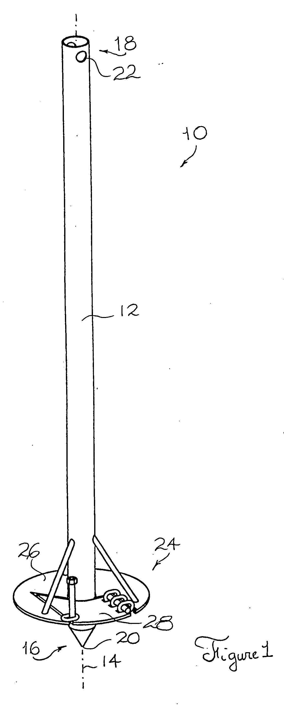
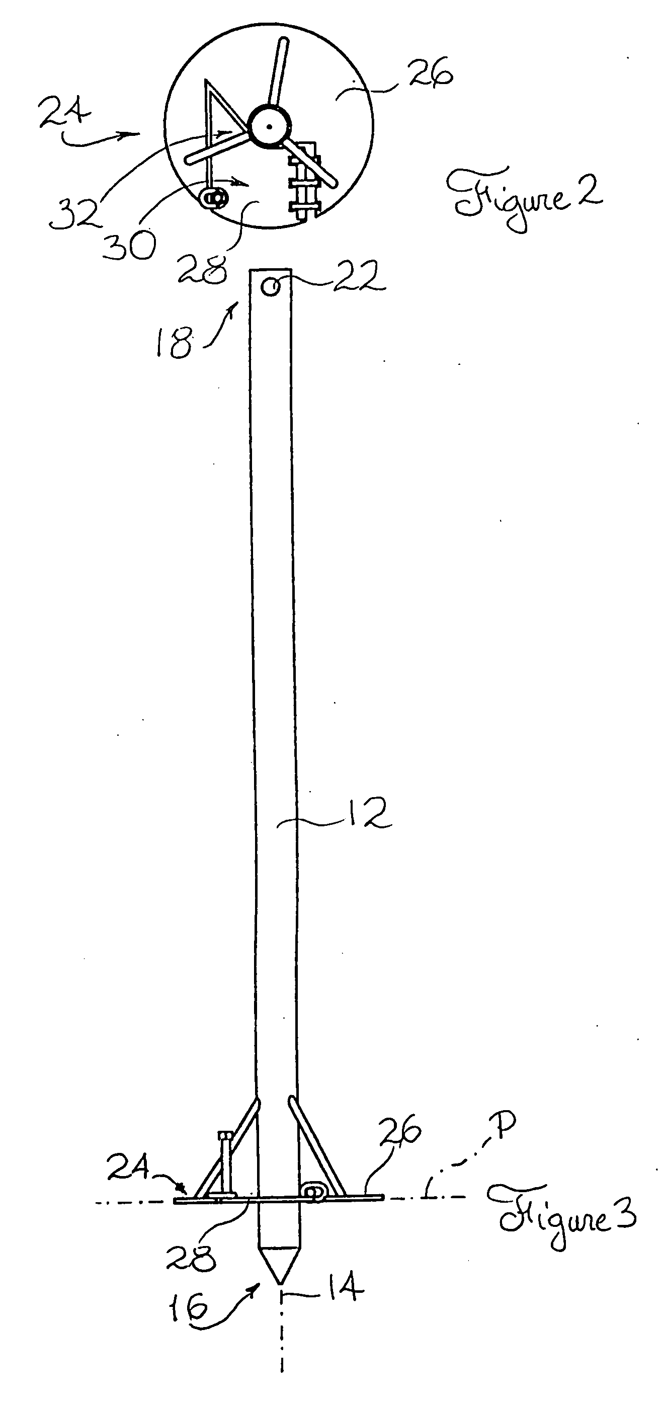
[0039] Referring to FIG. 1, there is shown an anchoring device in accordance with an embodiment of the present invention, generally indicated by the reference numeral 10. The anchoring device 10 is intended to be used mainly for anchoring an object (not shown) into a ground material (also not shown). The object may take any suitable form such as that of a car shelter, a tent, a balcony or any other suitable object without departing from the scope of the present invention. Also, the ground material may take any suitable form such as that of earth, sand, clay or any other suitable ground material without departing from the scope of the present invention.

[0040] Typically, the anchoring device is adapted to be anchored into the ground material using a driving tool (not shown) for providing a rotational driving force. Alternatively, the anchoring device 10 could be anchored into the ground manually. It should be understood that various types of driving tools could be used together with ...


PUM


Abstract

An anchoring including a stake and a flange extending radially outwardly from the stake. The flange has a flange fixed section and a flange movable section movably attached to the flange fixed section. The flange movable section is selectively movable between an aligned configuration and an angled configuration, wherein in the flange angled configuration, the flange movable section is angled relative to the flange fixed section and, in the flange aligned configuration, the flange movable section is in a substantially co-planar relationship relative to the flange fixed section. The flange movable section is adapted to act as an auger for facilitating the insertion of the stake in the ground material when in the flange angled configuration and to co-operate with the flange fixed section when in the flange aligned configuration to assist in stabilising the stake in the ground material.

Description

FIELD OF THE INVENTION [0001] The present invention relates to the field of anchoring devices and is more particularly concerned with an anchoring device having a flange for acting selectively as an auger blade or a stabilizing plate. BACKGROUND OF THE INVENTION [0002] There exists a plurality of situations wherein it is desirable to solidly anchor objects such as temporary vehicle shelters, balconies or the like to a ground material. Typically, the object being anchored needs to be prevented from being lifted from the ground and / or sinking into the ground. [0003] The prior art is replete with various anchoring devices for anchoring various types of objects. One of the drawbacks associated with some prior art anchoring devices relates to the relative difficulty with which they can be inserted into the ground. In order to facilitate insertion into the ground, some prior art devices are provided with auger-type blades. Such auger-type blades are adapted to act like a screw thread or p...

Claims


Application Information

Patent Timeline
IPC IPC(8): B65D63/00E02D5/80
CPCE02D5/801
Inventor PLANTE, DANIEL
Owner PLANTE DANIEL
Why Eureka
Try Eureka