

Portable electronic device
- Summary
- Abstract
- Description
- Claims
- Application Information
AI Technical Summary
Benefits of technology
Problems solved by technology
Method used
Image

Examples
first embodiment
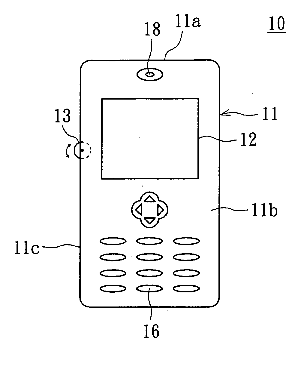
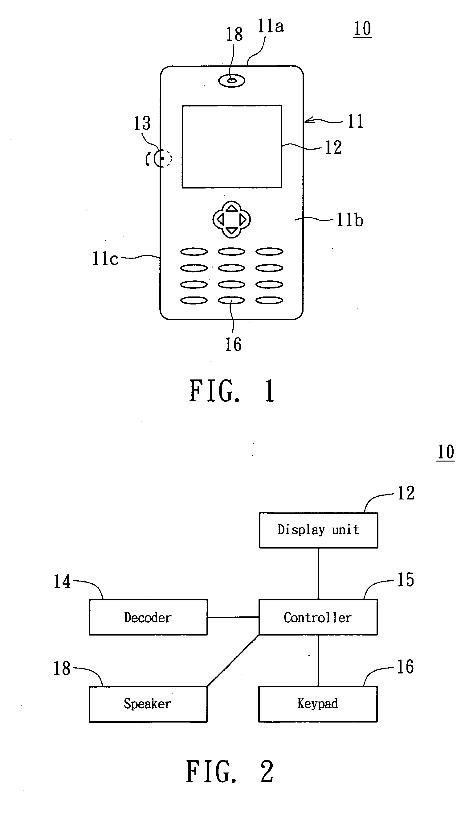
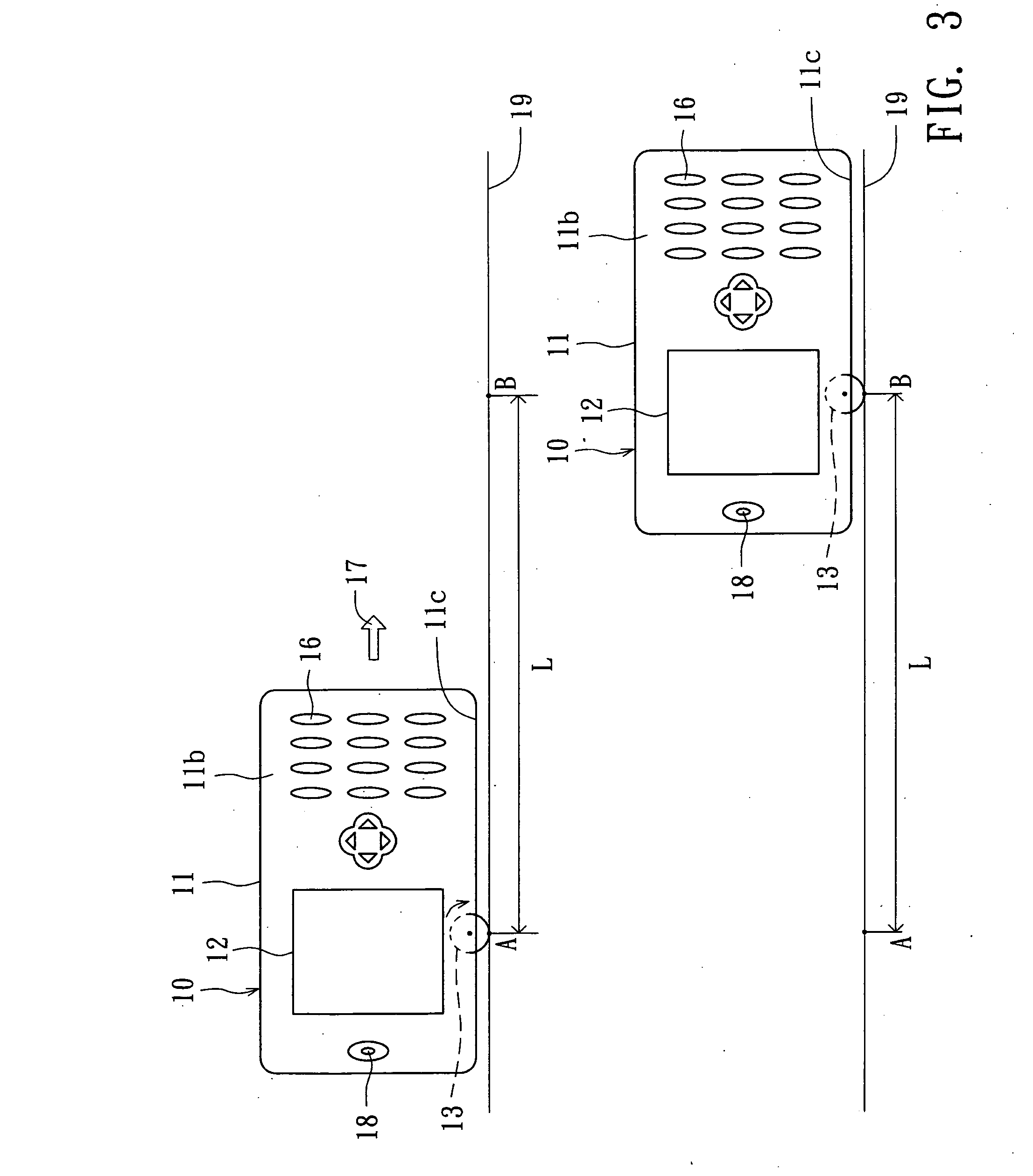
[0022] Referring to FIGS. 1˜2, FIG. 1 is a diagram of a portable electronic device according to a first embodiment of the invention, and FIG. 2 is a circuit block diagram of the portable electronic device according to the first embodiment of the invention. In FIGS. 1˜2, the portable electronic device 10 selectively works at a voice-adjusting mode and a length-measuring mode for a user to selectively adjust the voice of the portable electronic device 10 and measure a length on a surface. The portable electronic device 10 includes a casing 11, a display unit 12, a roller 13, an encoder 14 and a controller 15. The casing 11 has a casing surface 11a. The display unit 12 is disposed on the casing surface 11a for displaying a screen frame. The roller 13 is rotatably disposed on the casing surface 11a with a portion of the roller 13 being exposed outside the casing 11. When the portable electronic device 10 works at the voice-adjusting mode, the roller 13 is for the user to adjust the voic...
second embodiment
[0040] Referring to FIGS. 8˜9, FIG. 8 is a diagram of a portable electronic device according to a second embodiment of the invention, and FIG. 9 is a circuit block diagram of a portable electronic device according to a second embodiment of the invention. The portable electronic device 30 of the present embodiment differs with the portable electronic device 10 of the first embodiment in that function switch 27 of the portable electronic device 30 enables the user to selectively switch the portable electronic device 30 between the voice-adjusting mode and the length-measuring mode. As for the same components, the same labels are used and their relationships are not repeated here.
[0041] In FIGS. 8˜9, the function switch 17 is disposed on the casing surface 11a. For example, the function switch 17 can be disposed on the casing front surface 11b to be electrically connected to the controller 15. The function switch 17 is touched to output a switch signal, so that the controller 15 switc...
third embodiment
[0044] Referring to FIG. 10, a diagram of a portable electronic device a according to a third embodiment of the invention is shown. The portable electronic device 40 of the present embodiment differs with the portable electronic device 10 of the first embodiment in that the display unit 12 has a function menu 12a for selectively switching the portable electronic device 40 between the voice-adjusting mode and the length-measuring mode. As for the same components, the same labels are used and their relationships are not repeated here.
[0045] In FIG. 10, the function menu 12a has a volume-adjusting item 12b and a length-measuring item 12c. When the user operates to select the volume-adjusting item 12b via the keypad 16 or other operating interface, the portable electronic device 10 is switched to the voice-adjusting mode. Meanwhile, the user can rotate the roller 13 to adjust the voice of the portable electronic device 40. For example, the voice of the speaker 18 is adjusted. When the ...
PUM
 Abstract
Description
Claims
Application Information