Projection type display unit

Inactive Publication Date: 2006-11-30
SONY CORP
View PDF14 Cites 17 Cited by
  • Summary
  • Abstract
  • Description
  • Claims
  • Application Information

AI Technical Summary

Benefits of technology

[0011] In the projection type display unit according to the present invention configured as above, by the heat diffusing effect of the highly heat conductive sheet metal component part disposed between the lamp and the armor cabinet and the heat insulating effect of the lowly heat conductive heat insulating sheet, it is possible to lower the te

Problems solved by technology

However, in the structure according to Patent Reference 1, it is necessary to provide a large space between the lamp and the armor cabinet, so that the thickness of

Method used


Image

  • Projection type display unit
  • Projection type display unit
  • Projection type display unit

Examples


Embodiment Construction

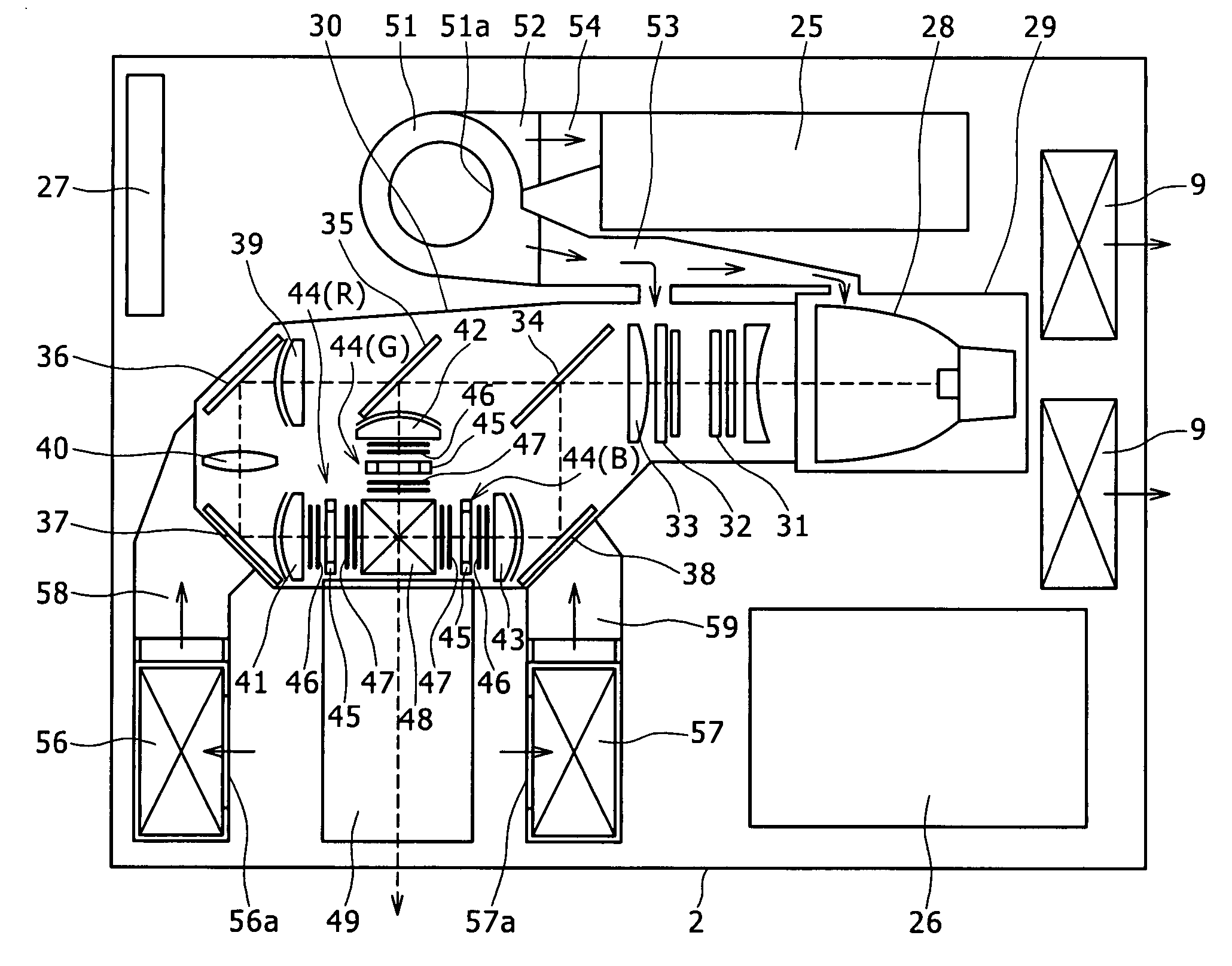
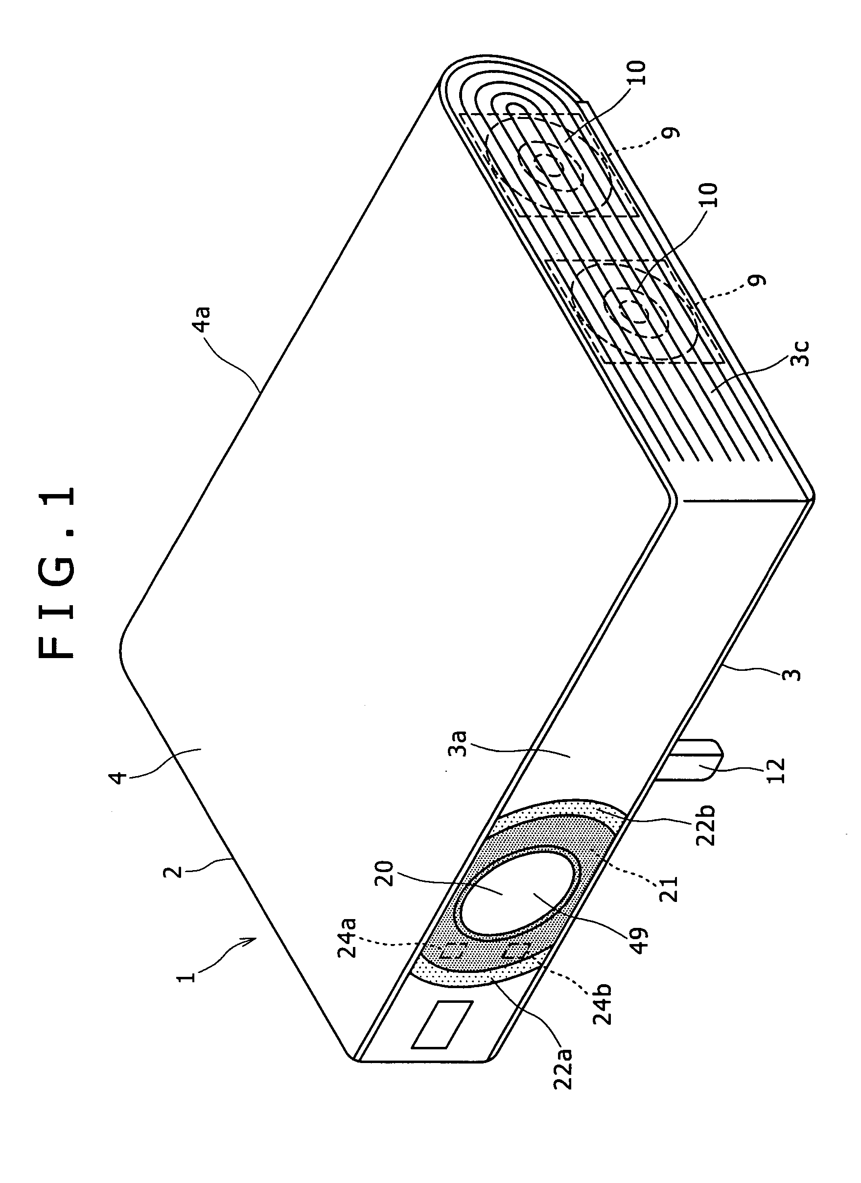
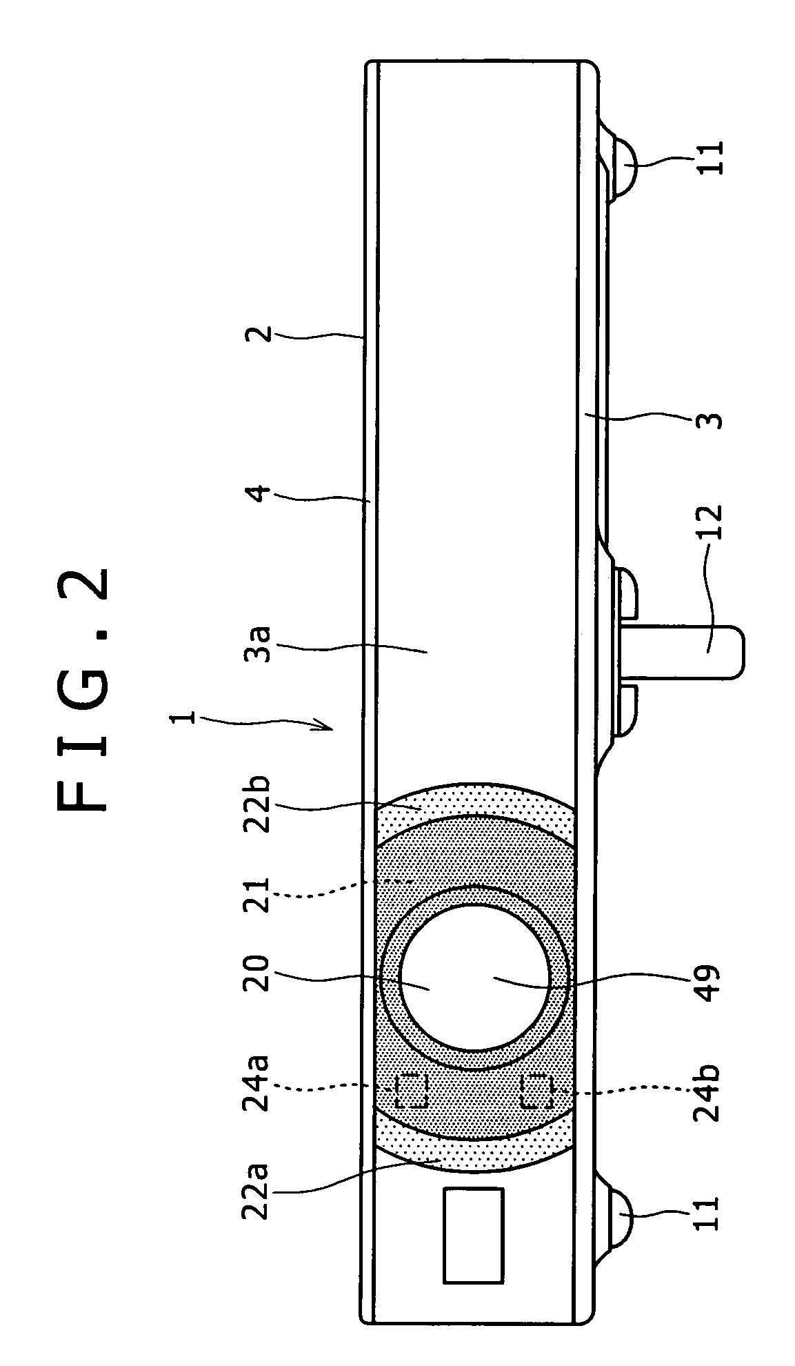
[0029] Now, an embodiment of the projection type display unit according to the present invention will be described in detail below, referring to the drawings. FIGS. 1 to 5 show the appearance of the projection type display unit in this embodiment, wherein FIG. 1 is a perspective view, FIG. 2 is a front view, FIG. 3 is a left side view, FIG. 4 is a right side view, and FIG. 5 is a bottom view. In addition, FIG. 6 is a plan view showing the inside structure of the projection type display unit in this embodiment.

[0030] The projection type display unit 1 shown here is a video projector which is of a small and thin type having a B5 size with a thickness of 50 mm or below, and in which light-weight is realized to have a weight of about 1.8 kg.

[0031] As shown in FIG. 6, the projection type display unit 1 has a configuration in which a lamp unit 29 containing a lamp 28 as a light source, and an optical unit 30 including three color light valves 44(R), 44(G), 44(B) and a projection lens 49...


PUM


Abstract

The present invention provides a projection type display unit including a light source, an optical unit including a light valve and a projection lens, and a cooling section for cooling the light source and the optical unit. The light source and the optical unit as well as the cooling section are incorporated in an armor cabinet. A highly heat conductive sheet metal component part is disposed in a space between a lamp as the light source and the armor cabinet.

Description

CROSS REFERENCES TO RELATED APPLICATIONS [0001] The present invention contains subject matter related to Japanese Patent Application JP 2005-154153 filed in the Japanese Patent Office on May 26, 2005, the entire contents of which being incorporated herein by reference. BACKGROUND OF THE INVENTION [0002] The present invention relates to a projection type display unit such that an image obtained by irradiating a light valve or valves with light from a light source is projected onto a screen or the like for displaying the image, particularly to a heat release structure for a projection type display unit. [0003] A projection type display unit generally called video projector has a configuration in which a light source, an optical unit including light valves and a projection lens, and a cooling section for cooling the light source and the optical unit are incorporated in an armor cabinet. The projection type display unit is a unit in which an image obtained by irradiating the light valve...

Claims


Application Information

Patent Timeline
IPC IPC(8): G03B21/18G03B21/26
CPCG03B21/26G03B21/18G03B21/00G03B21/16
Inventor NASU, TAKASHIOHKUBO, TAKUJISAITO, MASAHIROWADA, YOSHIHISA
Owner SONY CORP
Why Eureka
Try Eureka