
Kinetic sculpture and method of assembling same

a kinetic sculpture and sculpture technology, applied in toys, entertainment, domestic applications, etc., can solve the problems of limiting the configuration of the overall shape of the sculpture, contributing significantly to the cost of manufacturing the sculpture, etc., and achieve the effect of reducing skill and time and broadening the possible configurations

Inactive Publication Date: 2006-11-30
SATER NEIL A +1
View PDF18 Cites 11 Cited by
  • Summary
  • Abstract
  • Description
  • Claims
  • Application Information

AI Technical Summary

Benefits of technology

"The present invention is a kinetic sculpture that can be easily assembled without brazing, welding, or soldering the vanes to each other. This reduces the time and skill required for manufacturing. The invention also allows for a variety of configurations, making it more aesthetically pleasing. The kinetic sculpture comprises an axis of rotation, a plurality of spiral vanes, and first and second assembly members. The vanes have longitudinal lengths that spiral about the axis of rotation and opposite first and second longitudinal end margins. The first assembly member connects the first end margin of each vane to each other in a manner such that the first end margins are circumferentially spaced from each other about the axis of rotation and the orientation plane of the first end margin is oriented at most five degrees from parallel to the axis of rotation. The second assembly member connects the second end margin of each vane to each other in a manner such that the second end margin is at least partially positioned within one of the slots of the second assembly member. The invention also includes a method of assembling a kinetic sculpture by providing a plurality of spiral vanes, attaching the first end margin of each vane to the first assembly member, and connecting the second end margin of each vane to the second assembly member. The technical effects of the invention include reducing the time and skill required for manufacturing, allowing for a variety of configurations, and improving the aesthetic appearance of kinetic sculptures."

Problems solved by technology

This step of securing the vanes to each other requires appreciable skill and time, which contributes significantly to the costs of manufacturing the sculptures.
Additionally, this step typically requires the vanes of the sculpture to overlap each other at their opposite ends and thereby limits the possible configurations of the overall shape of the sculptures.

Method used


Image

  • Kinetic sculpture and method of assembling same
  • Kinetic sculpture and method of assembling same
  • Kinetic sculpture and method of assembling same

Examples


Embodiment Construction

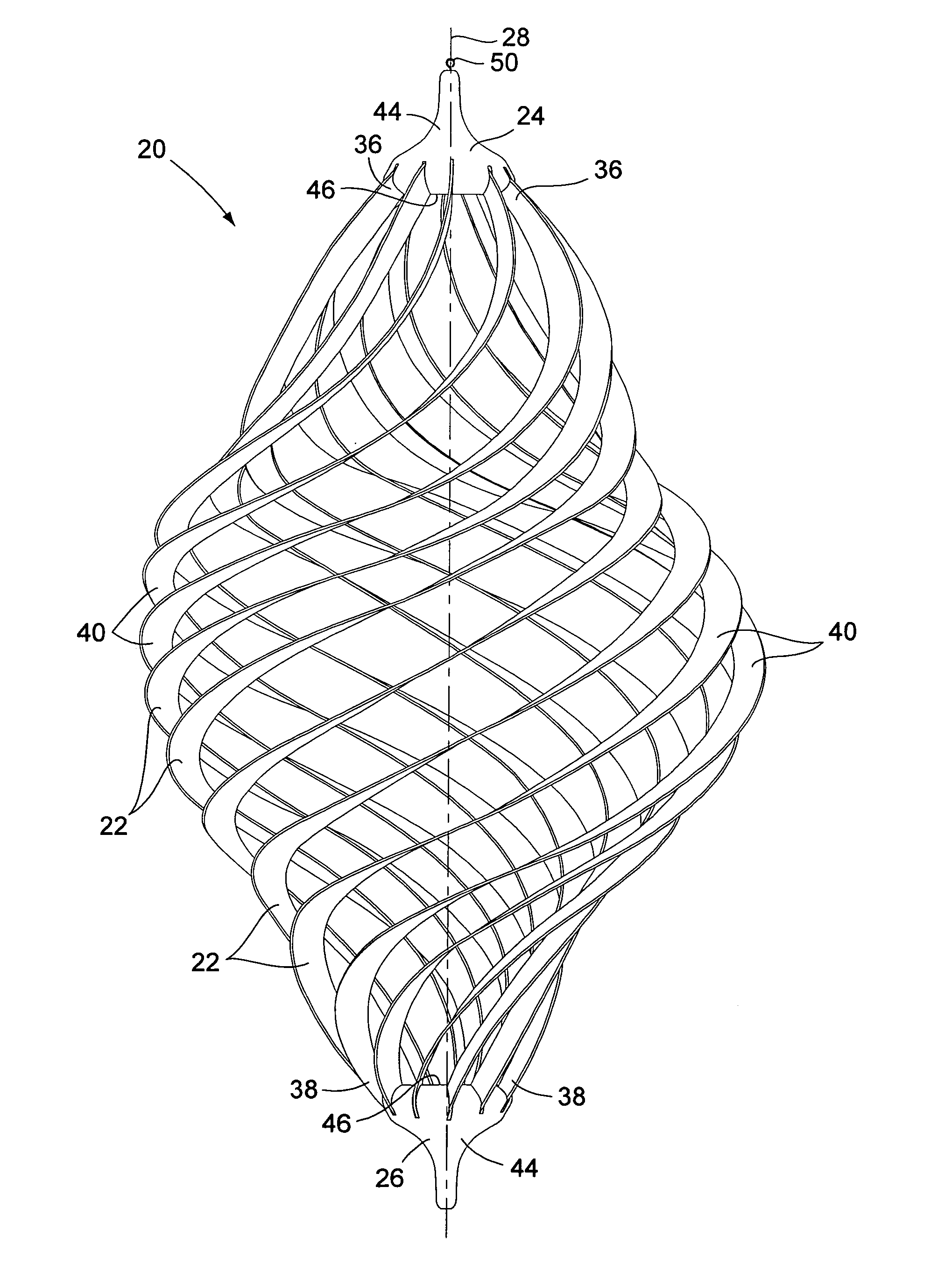
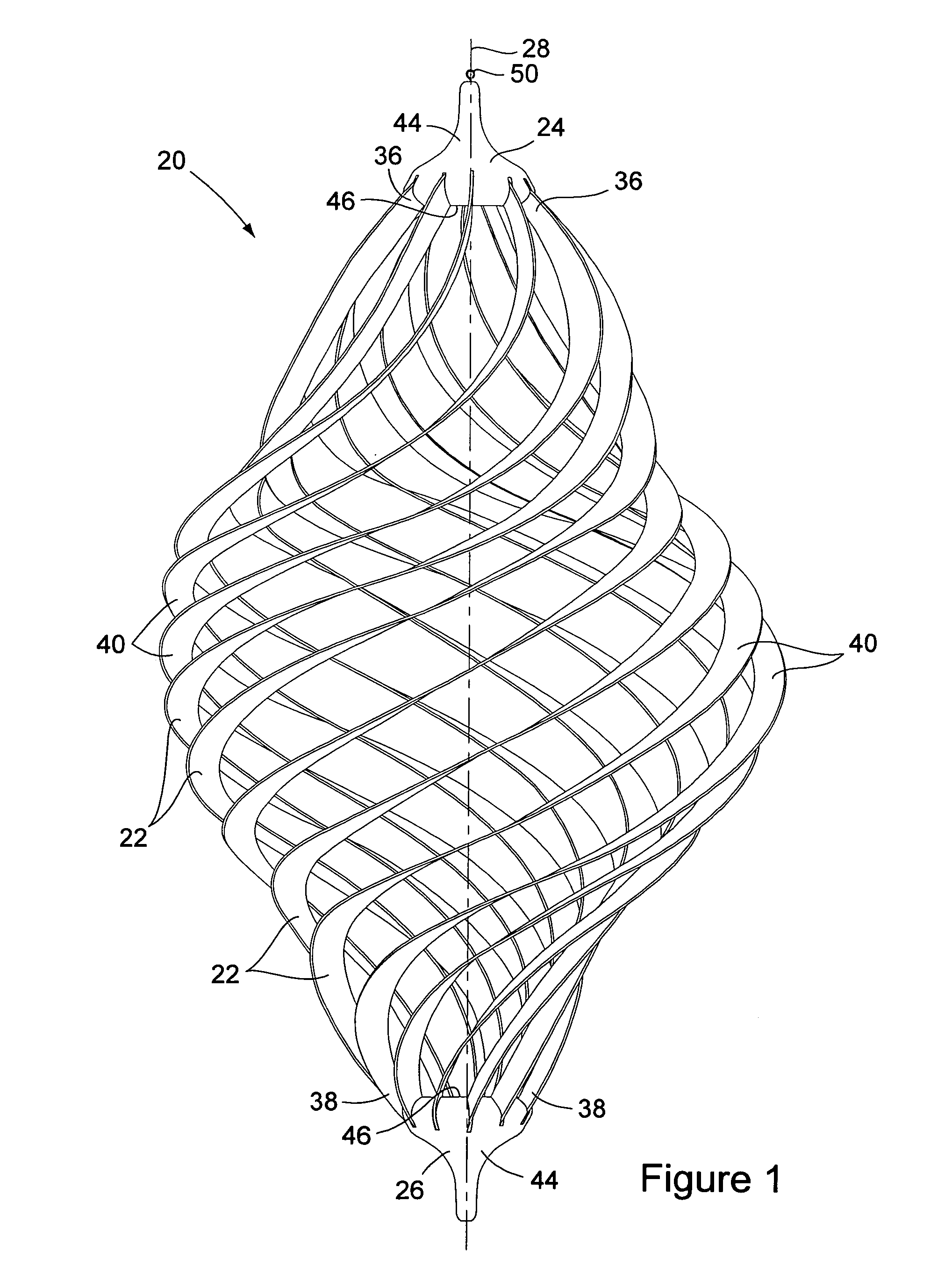
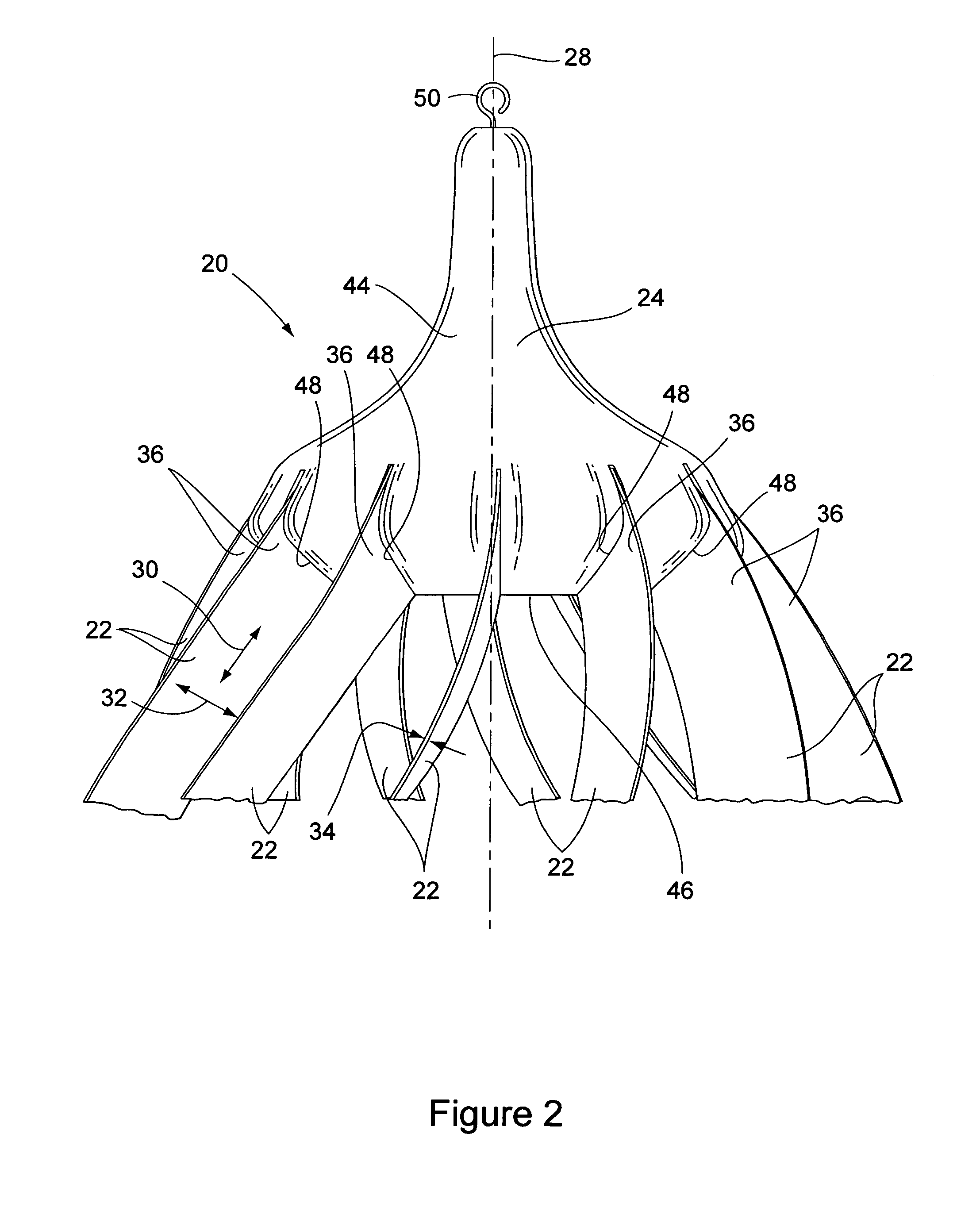
[0017] A first embodiment of a kinetic sculpture 20 of the present invention is shown in its entirety in FIG. 1. The kinetic sculpture 20 preferably comprises a plurality of vanes 22 and top 24 and bottom 26 assembly members. The vanes 22 are preferably formed out of metal, such as copper, and may be coated with decorative finishes or allowed to patina. The assembly members may be formed out plastic, metal, wood, or any other suitable materials.

[0018] The vanes 22 of the kinetic sculpture 20 are preferably identical in shape and spiral about the axis of rotation 28 of the kinetic sculpture. Each vane 22 is preferably die cut in a spiral pattern from a flat piece of sheet material and is thereafter stretched out of plane such that the vane longitudinally extends along the axis of rotation 28 as it spirals thereabout. Each vane 22 has a longitudinal length 30, a width 32, and a thickness 34 that are mutual transverse to each other at each point along the vane. Additionally, each vane...


PUM


Abstract

A kinetic sculpture comprises an axis of rotation, a plurality of spiral vanes, and a first assembly member. Each of the vanes has a longitudinal length that spirals about and along the axis of rotation and opposite first and second longitudinal end margins. The first assembly member connects the first end margin of each of the vanes to each other in a manner such that the first end margins of the vanes are circumferentially spaced from each other about the axis of rotation.

Description

BACKGROUND OF THE INVENTION [0001] (1) Field of the Invention [0002] The present invention pertains to the field of three-dimensional, geometric sculptures. More particularly, the present invention pertains to a kinetic sculpture comprising a plurality of spiral vanes that is configured to rotate about an axis of rotation and to a method of assembling the same. [0003] (2) General Background [0004] Spiral kinetic sculptures are popular as home and garden decorations and various types of spiral kinetic sculptures exist. One type of kinetic sculpture that has been very successful comprises a plurality of thin spiral vanes that spiral about a common axis of rotation. The vanes of such sculptures are often formed of metal and are often blade-like in that the width of each vane is typically many times larger than the its thickness. [0005] In use, a spiral kinetic sculpture is often suspended from a line or chain in a manner such that the sculpture is generally free to rotate about a verti...

Claims


Application Information

Patent Timeline
Patent Type & Authority Applications(United States)
IPC IPC(8): A47G35/00A63H1/00
CPCA63H1/00
Inventor SATER, NEIL A.CUNNINGHAM, ROBERT DAN
Owner SATER NEIL A
Learn More