Cell, connected-cell body, and battery module using the same

a connected cell and battery module technology, applied in the manufacture of cell components, cell component details, final product manufacturing, etc., can solve the problems of increasing the output and enhancing life characteristics, increasing the cost, and affecting the production efficiency of cells, so as to reduce the internal resistance per cell, increase the output, and increase the output

Active Publication Date: 2006-11-30
PANASONIC CORP +1
View PDF2 Cites 5 Cited by
  • Summary
  • Abstract
  • Description
  • Claims
  • Application Information

AI Technical Summary

Benefits of technology

[0013] An object of the present invention is to decrease the internal resistance per cell, thereby increasing the output, and to enable the entire electrode plate group to provide the intrinsic capability, thereby increasing the output in a battery module storing a plurality of cells. Another object is to provide a cell and a connected-cell body for realizing this battery module.
[0015] With the constitution of the first aspect, the current-carrying paths to the individual leads and the collectors from the positive electrode plate and the negative electrode plate of the electrode plate group serving as a power generation element of the cell is shortened. Further, since the collectors are connected with each other at an arbitrary position by directly joining the connection protrusions when the cells are connected with each other, the current-carrying path is shortened. At the same time, the number of the connection points can be increased. Thus, the internal resistance is reduced, and consequently, the internal resistance per cell is reduced further accordingly, thereby increasing the output. In addition, since the distribution of the current flowing through the electrode plate group is equalized by providing a plurality of connection protrusions on the individual collectors, the entire electrode plate group provides the capability, thereby increasing the output further. In a battery module containing a plurality of cells in prismatic shape, since it is not necessary to provide a partition wall between the cells, the prismatic battery case is compact accordingly.
[0021] With the constitution of the fifth aspect, since the collectors are joined to the leads on both sides of the electrode plate group, the individual electrode plates and the collectors are joined straight, and the distance between them is short consequently. Since the connection members for outside connection are connected with the middle part of the collectors through the connection openings on the bag-shape battery case, there are no additional connection members or connection points, and simultaneously the current-carrying paths of the collectors are short. Thus, the internal resistance is low. Further, since the connection member is connected with the middle part of the collectors, the distribution of the current flowing through the electrode plate group is equalized especially when the plurality of connection members are connected. Thus, the entire electrode plate group provides uniform power generation capability, and the output increases consequently. In addition, since the connection opening formed on the bag-shape battery case for joining the connection member is surely sealed by the seal material compressed by the connection member joined through the connection opening, the seal of the bag-shape battery case is secured.

Problems solved by technology

As a result, since connection paths between the cells are long, and the number of connection points is large, resistance caused by constitution parts including connection parts becomes high.
Since this large internal resistance increases heat generation, increasing the output and enhancing life characteristics are seriously obstructed.
Also, since the connection constitution between the cells is complicated, and the number of the parts is large, the cost also increases.
Consequently, the distribution of the current flowing through the electrode plate group 108 becomes uneven, thus the entire electrode plate group 108 does not present uniform power generation capability, and consequently the loss increases.

Method used


Image

  • Cell, connected-cell body, and battery module using the same
  • Cell, connected-cell body, and battery module using the same
  • Cell, connected-cell body, and battery module using the same

Examples


first embodiment

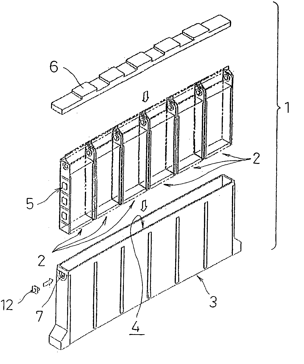
[0042] a battery module of the present invention will be described referring to FIG. 1 to FIG. 12B.

[0043] In FIG. 1, a battery module 1 of the present embodiment includes a prismatic battery case 3. The prismatic battery case 3 has a horizontally oblong box shape, and forms a storage space 4 for storing a connected-cell body 5 including a plurality of (six in the drawing) cells 2. The connected-cell body 5 is formed by connecting the plurality of prismatic cells 2, including short side surfaces and long side surfaces, with each other at their short side surfaces. Connection holes 7 for installing and connecting a connection terminal 12 are formed on an upper part on both end walls of the prismatic battery case 3. In addition, a top opening of the prismatic battery case 3 is sealed by adhering a cover 6.

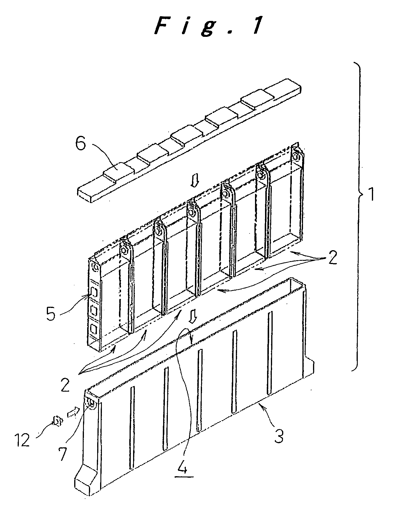
[0044] An electrode plate group 8 is constituted such that a plurality of positive electrode plates and negative electrode plates are alternately laminated with separators interposed...

second embodiment

[0069] The following section will describe a cell and a connected-cell body of the present invention which are preferably used for the battery module 1 described above while referring to FIG. 13 to FIG. 15.

[0070] In FIG. 13 to FIG. 15, a connected-cell body 40 is constituted by connecting a plurality of (only two in the drawing) cells 41. The cell 41 is constituted by storing an electrode plate group 43 including collectors 44 joined on both ends along with electrolyte in a bag-shape battery case 42.

[0071] The bag-shape battery case 42 is constituted by joining a single-layer or multi-layer-laminated synthetic resin sheet 45 made of polypropylene or polyethylene into a bag shape by heat adhesion or adhesion with adhesive. Specifically, the synthetic resin sheet 45 with a thickness of 100 to 150 mm is wound on the electrode plate group 43 so as to surround it. Then, both side edges are joined by heat seal, and the bottom end of the tubular synthetic resin sheet 45 formed in this way...


PUM

PropertyMeasurementUnit
thicknessaaaaaaaaaa
polaritiesaaaaaaaaaa
heataaaaaaaaaa

Abstract

A cell includes an electrode plate group which is formed by laminating a positive electrode plate and a negative electrode plate with a separator interposed between them, and includes leads protruding toward directions opposite to each other from one side of the positive electrode plate and the negative electrode plate. Collectors are joined to the leads on both sides of the electrode plate group, and include connection protrusions formed so as to protrude outside. A bag-shape battery case containing the electrode plate group is joined to the collectors such that only the connection protrusions of the collectors are protruded outside the bag-shaped battery case. A battery module is constituted by placing a plurality of the cells, connected together, into a prismatic battery case.

Description

[0001] This is a Divisional application of Ser. No. 10 / 213,822 filed Aug. 6, 2002. [0002] The present disclosure relates to subject matter contained in priority Japanese Patent Application Nos. 2001-237753, 2002-9510, and 2002-14702 filed on Aug. 6, 2001, Jan. 18, 2002, and Jan. 23, 2002 respectively, the contents of which is herein expressly incorporated by reference in its entirety.BACKGROUND OF THE INVENTION [0003] 1. Field of the Invention [0004] The present invention relates to a cell, a connected-cell body, and a battery module using the same, and more particularly to a cell for reducing the internal resistance, a connected-cell body, and a battery module using the same. [0005] 2. Description of Related Art [0006] A conventional battery module for providing a required electric power capacity by connecting a plurality of cells is constituted such that a plurality of individual prismatic cells are placed while longer side surfaces of their battery case are opposingly brought int...

Claims


Application Information

Patent Timeline
Patent Type & Authority Applications(United States)
IPC IPC(8): H01M2/02H01M2/08H01M10/04H01M50/186H01M50/529
CPCH01M2/0217H01M10/04H01M2/24H01M2/08Y02E60/10H01M50/103H01M50/529Y02P70/50H01M50/186
Inventor ASAHINA, TAKASHIFUKUDA, SHINSUKEHAMADA, SHINJIETO, TOYOHIKOONISHI, MASATO
Owner PANASONIC CORP
Why Eureka
Try Eureka