Orthodontic bracket

a technology for orthodontic brackets and brackets, applied in the field of pre-engaging orthodontic brackets, can solve the problems of increasing the friction level, long chair time, and elastic ligatures are known to lose their elasticity with time, and achieve the effect of enhancing treatment progress and facilitating hygien

Inactive Publication Date: 2006-11-30
ORTHOARM
View PDF33 Cites 30 Cited by
  • Summary
  • Abstract
  • Description
  • Claims
  • Application Information

AI Technical Summary

Benefits of technology

[0028] The present invention provides advantages in that the orthodontic brackets provide predictability and accurate control of tooth movement while enhancing treatment progress. The orthodontic brackets are aesthetically pleasing due to their symmetrical designs and provide for easier hygiene than prior art orthodontic brackets.

Problems solved by technology

It has been found that the time-consuming ligation procedure contributes to lengthy chair time.
Furthermore, the elastic ligatures are known to lose their elasticity with time and are subject to degradation.
Also, the elastic and metal ligatures have been known to trap food particles in areas of the bracket which are difficult for the patient to clean, and to increase the level of friction against the archwire.
Finally, the use of sharp metal ligatures around the bracket can subject the clinician to unnecessary exposure to infectious bacteria, or viruses such as hepatitis B, or possibly the HIV virus particularly in blood.
In addition, pre-engaging orthodontic brackets permit continuous low deflection differential archwire contact separately for both round and rectangular archwires at at least two different levels of contact, which is not possible with degrading elastic, elastomeric or rigid, high deflection metal ligatures.
However, most of the known prior art pre-engaging orthodontic brackets lack the reliability and the accessible ease of operability that most clinicians require.

Method used


Image

  • Orthodontic bracket
  • Orthodontic bracket
  • Orthodontic bracket

Examples


Embodiment Construction

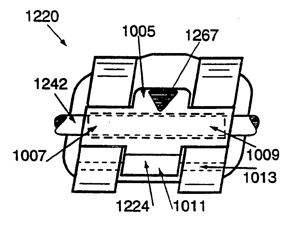
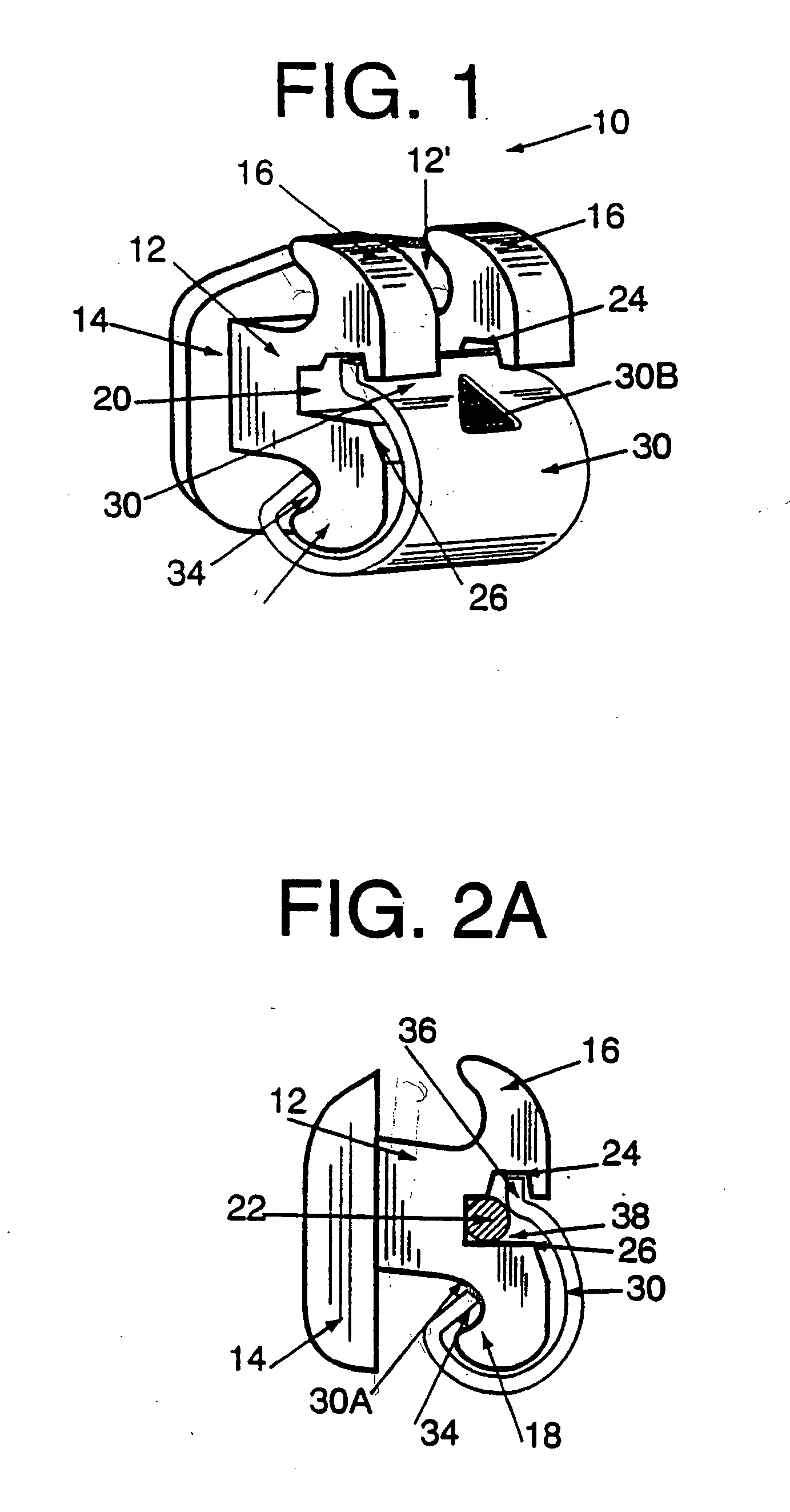
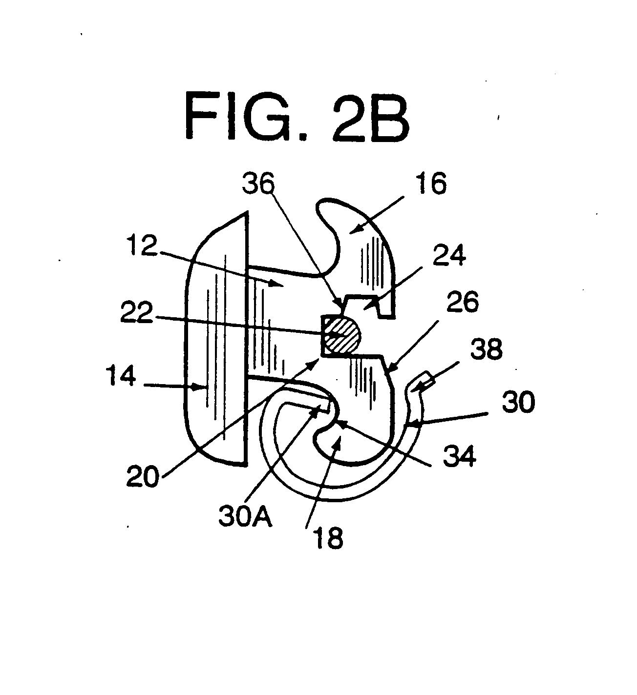
[0147] Referring now to FIGS. 1 and 2, a pre-engaging twin orthodontic bracket is shown and is generally indicated to by reference numeral 10. As can be seen, orthodontic bracket 10 includes a body 12 and a lingual mounting pad 14 attached to the body. The mounting pad 14 has a lingual surface to be attached to a tooth. A pair of laterally spaced gingival tie wings 16 and a pair of laterally spaced occlusal tie wings 18 extend from a labial surface of the body 12. The gingival tie wings 16 and the occlusal tie wings 18 curve lingually. An archwire slot 20 extends mesiodistally across the body and between the gingival and occlusal tie wings at opposed mesial and distal sides of the body and opens labially to receive an archwire 22. The archwire slot 20 is interrupted in the interwing region 12′ of the body. A V-shaped deflection notch is formed in the gingival wall of the archwire slot 20 at its mesial and distal ends extends to define mesial and distal bevelled deflection surfaces 2...


PUM


Abstract

In one embodiment, a pre-engaging orthodontic bracket includes a body having a lingual surface for attachment to a tooth, a pair of laterally spaced gingival tie wings and a pair of laterally spaced occlusal tie wings. The gingival and occlusal tie wings project from a labial surface of the body. An archwire slot extends mesiodistally across the body and between the gingival and occlusal tie wings at opposed mesial and distal sides of the body to accommodate an archwire. A pivot pin extends between a pair of the tie wings at opposed mesial and distal sides of the body. A shutter is moveable relative to the body between an open position in which placement and removal of an archwire into the archwire slot is facilitated and a closed position in which placement and removal of an archwire into the archwire slot is inhibited.

Description

RELATED APPLICATIONS [0001] The present application is a continuation-in-part of U.S. application Ser. No. 08 / 625,944, filed on Apr. 1, 1996 which is a continuation-in-part of U.S. application Ser. No. 08 / 412,338 filed on Mar. 31, 1995 now abandoned which is a continuation-in-part of U.S. application Ser. No. 08 / 206,724 filed on Mar. 7, 1994 now issued and granted under U.S. Pat. No. 5,474,445.FIELD OF THE INVENTION [0002] The present invention relates in general to pre-engaging orthodontic brackets and in particular to a pre-engaging twin orthodontic bracket and to a plurality of orthodontic brackets forming a set of braces. BACKGROUND OF THE INVENTION [0003] According to established orthodontic techniques, it is well known that one is able to ligate an archwire to a bracket utilizing an elastic, elastomeric or metal ligature. In a twin edgewise orthodontic bracket, the elastic ligature is stretched around respective undercuts of gingival and occlusal tie wings so as to overlay the...

Claims


Application Information

Patent Timeline
Patent Type & Authority Applications(United States)
IPC IPC(8): A61C3/00A61C7/00A61C7/02A61C7/28
CPCA61C7/006A61C7/02A61C7/287A61C7/285A61C7/28
Inventor VOUDOURIS, JOHN C.
Owner ORTHOARM
Why Eureka
Try Eureka