In-plane switching liquid crystal display device and method

a liquid crystal display and switching technology, applied in non-linear optics, instruments, optics, etc., can solve the problem of bad color shift effect on the wide viewing angle of the ips-lcd device, and achieve the effect of preventing color shift or minimizing, improving viewing angle properties, and improving the viewing angl

Active Publication Date: 2006-12-07
LG DISPLAY CO LTD
View PDF7 Cites 23 Cited by
  • Summary
  • Abstract
  • Description
  • Claims
  • Application Information

AI Technical Summary

Benefits of technology

[0032] An advantage of the present invention is to provide an in-plane switching liquid crystal display device having improved viewing angle properties.
[0033] Another advantage of the present invention is to provide an in-plane switching liquid crystal display device in which a color shift is prevented or minimized.
[0034] Additional features and advantages of the invention will be set forth in the description which follows, and in part will be apparent from the description, or may be learned by practice of the invention. The advantages of the invention will be realized and attained by the structure particularly pointed out in the written description and claims hereof as well as the appended drawings.
[0035] To achieve these and other advantages and in accordance with the purpose of the present invention, as embodied and broadly described, an in-plane switching liquid crystal display device includes a first substrate, a second substrate spaced apart from the first substrate, a liquid crystal layer between the first and second substrates, a first polarizer at an outer surface of the first substrate, the first polarizer including a first polarization film and first inner and outer supporting film at both sides of the first polarization film, the first inner supporting film adjacent to the first substrate and having a retardation within a range of about −10 nm to about +10 nm, and a second polarizer at an outer surface of the second substrate, the second polarizer including a second polarization film and second inner and outer supporting film at both sides of the second polarization film, the second inner supporting film adjacent to the second substrate.
[0036] In another aspect of the present invention, a method of manufacturing a liquid crystal display device comprises providing first and second substrates; providing liquid crystal between the first and second substrates; providing a first polarizer on an outer surface of the first substrate, the first polarizer including a first polarization film and first inner and outer supporting films, at opposite sides of the first polarization film, the first inner supporting film adjacent to the first substrate and having a retardation value within a range of about −10 nm to about +10 nm; and providing a second polarizer on an outer surface of the second substrate, the second polarizer including a second polarization film and second inner and outer supporting films at opposite sides of the second polarization film, the second inner polarization film adjacent to the second substrate.
[0037] In a further aspect of the present invention, an in-plane switching liquid crystal display device, comprises a first substrate; a second substrate spaced apart from the first substrate; a liquid crystal layer between the first and second substrates; a first polarizer at an outer surface of the first substrate, the first polarizer including a first polarization film and first inner and outer supporting films at opposite sides of the first polarization film, the first inner supporting film adjacent to the first substrate; and a second polarizer at an outer surface of the second substrate, the second polarizer including a second polarization film and second inner and outer supporting films, at opposite sides of the second polarization film, the second inner supporting film adjacent to the second substrate wherein a color shift from viewing the in-plane switching liquid crystal display device is minimized to a range of about 0.2-0.3 for “x” coordinate and 0.2-0.3 for “y” coordinate in the CIE chromaticity diagram.

Problems solved by technology

The color shift has bad effect on a wide viewing angle of the IPS-LCD device.

Method used


Image

  • In-plane switching liquid crystal display device and method
  • In-plane switching liquid crystal display device and method
  • In-plane switching liquid crystal display device and method

Examples


Embodiment Construction

[0050] Reference will now be made in detail to an embodiment of the present invention, an example of which is illustrated in the accompanying drawings.

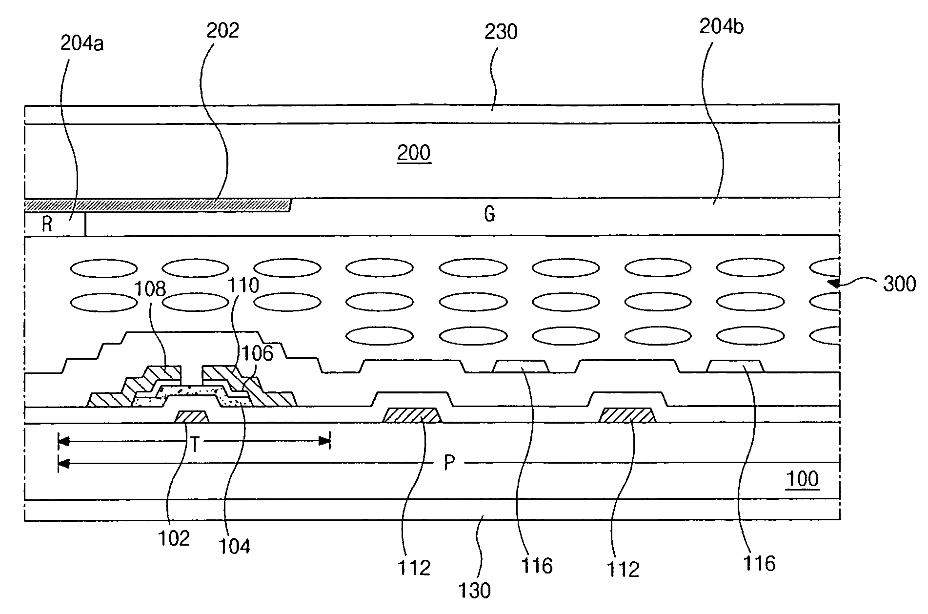
[0051]FIG. 6 is a cross-sectional view illustrating an IPS-LCD device according to an embodiment of the present invention. The IPS-LCD device includes an array substrate and a color filter substrate attached and spaced apart from each other. The IPS-LCD device further includes a liquid crystal layer interposed between the array substrate and the color filter substrate.

[0052] In FIG. 6, a pixel region P is defined on a first substrate 100. Although not shown in the figure, a plurality of gate lines and a plurality of data lines are formed on the first substrate 100 and cross each other to thereby define each pixel region P.

[0053] A thin film transistor T, as a switching element, is formed at each crossing point of the gate and data lines and is disposed in the pixel region P on the first substrate 100. The thin film transistor T inc...


PUM

PropertyMeasurementUnit
optical anisotropyaaaaaaaaaa
electric fieldaaaaaaaaaa
brightnessaaaaaaaaaa

Abstract

An in-plane switching liquid crystal display device includes a first substrate, a second substrate spaced apart from the first substrate, a liquid crystal layer between the first and second substrates, a first polarizer at an outer surface of the first substrate, the first polarizer including a first polarization film and first inner and outer supporting film at both sides of the first polarization film, the first inner supporting film adjacent to the first substrate and having a retardation within a range of about −10 nm to about +10 nm, and a second polarizer at an outer surface of the second substrate, the second polarizer including a second polarization film and second inner and outer supporting film at both sides of the second polarization film, the second inner supporting film adjacent to the second substrate.

Description

[0001] The present invention claims the benefit of Korean Patent Application No. 2005-0046745 filed on Jun. 1, 2005, which is hereby incorporated by reference for all purposes as if fully set forth herein. BACKGROUND OF THE INVENTION [0002] 1. Field of the Invention [0003] The present invention relates to a liquid crystal display (LCD) device. More particularly, the present invention relates to an in-plane switching liquid crystal display (IPS-LCD) device and method. [0004] 2. Discussion of the Related Art [0005] Liquid crystal display (LCD) devices use the optical anisotropy and polarization properties of liquid crystal molecules to produce an image. Liquid crystal molecules have a definite alignment as a result of their long, thin shapes and are arranged to have initial pretilt angles. The alignment direction can be controlled by applying an electric field. Specifically, variations in an applied electric field influence the alignment of the liquid crystal molecules. Due to the opt...

Claims


Application Information

Patent Timeline
Patent Type & Authority Applications(United States)
IPC IPC(8): G02F1/1343
CPCG02F1/134363G02F1/133528G02F1/1335
Inventor KIM, JIN-HOMOON, SUNG-O
Owner LG DISPLAY CO LTD
Why Eureka
Try Eureka