Plate concrete dowel system

a concrete and plate technology, applied in the direction of paving details, constructions, roads, etc., can solve the problems of horizontal movement relative to pour joints, and achieve the effect of facilitating the movement facilitating the centering of the dowel pla

Inactive Publication Date: 2006-12-07
SHAW & SONS
View PDF28 Cites 38 Cited by
  • Summary
  • Abstract
  • Description
  • Claims
  • Application Information

AI Technical Summary

Benefits of technology

[0025] A rib insert may be included with the disc dowel system to facilitate movement of the dowel plate within the pocket former such as may occur during relative movement between the first and second pours. The rib insert may be a separately installed component configured to be insertable into the pocket former and is preferably sized and shaped to fit within the interior compartment along the sides and end thereof...

Problems solved by technology

Horizontal movement relative to the pour joint may occur due to uncontrolle...

Method used


Image

  • Plate concrete dowel system
  • Plate concrete dowel system
  • Plate concrete dowel system

Examples


Embodiment Construction

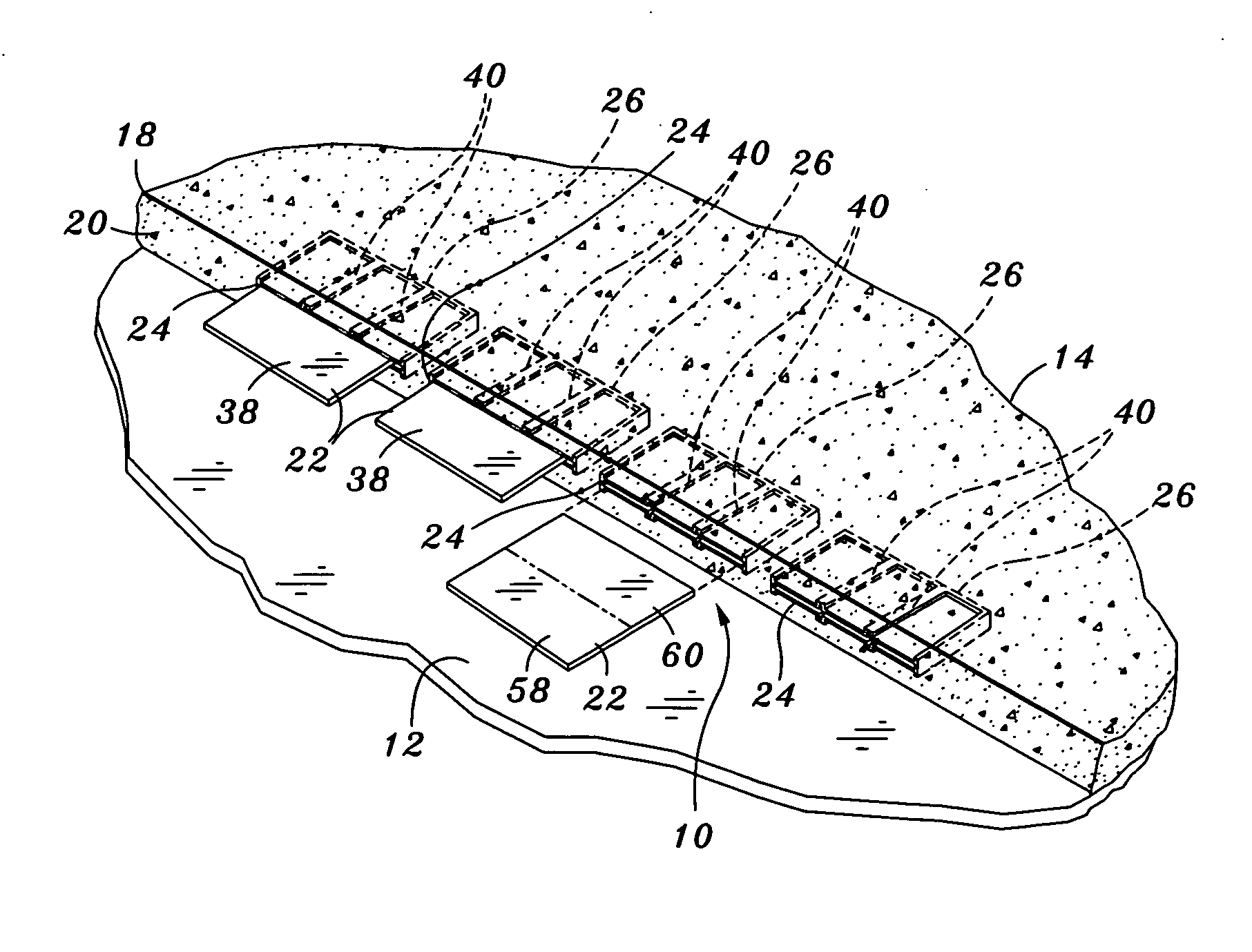
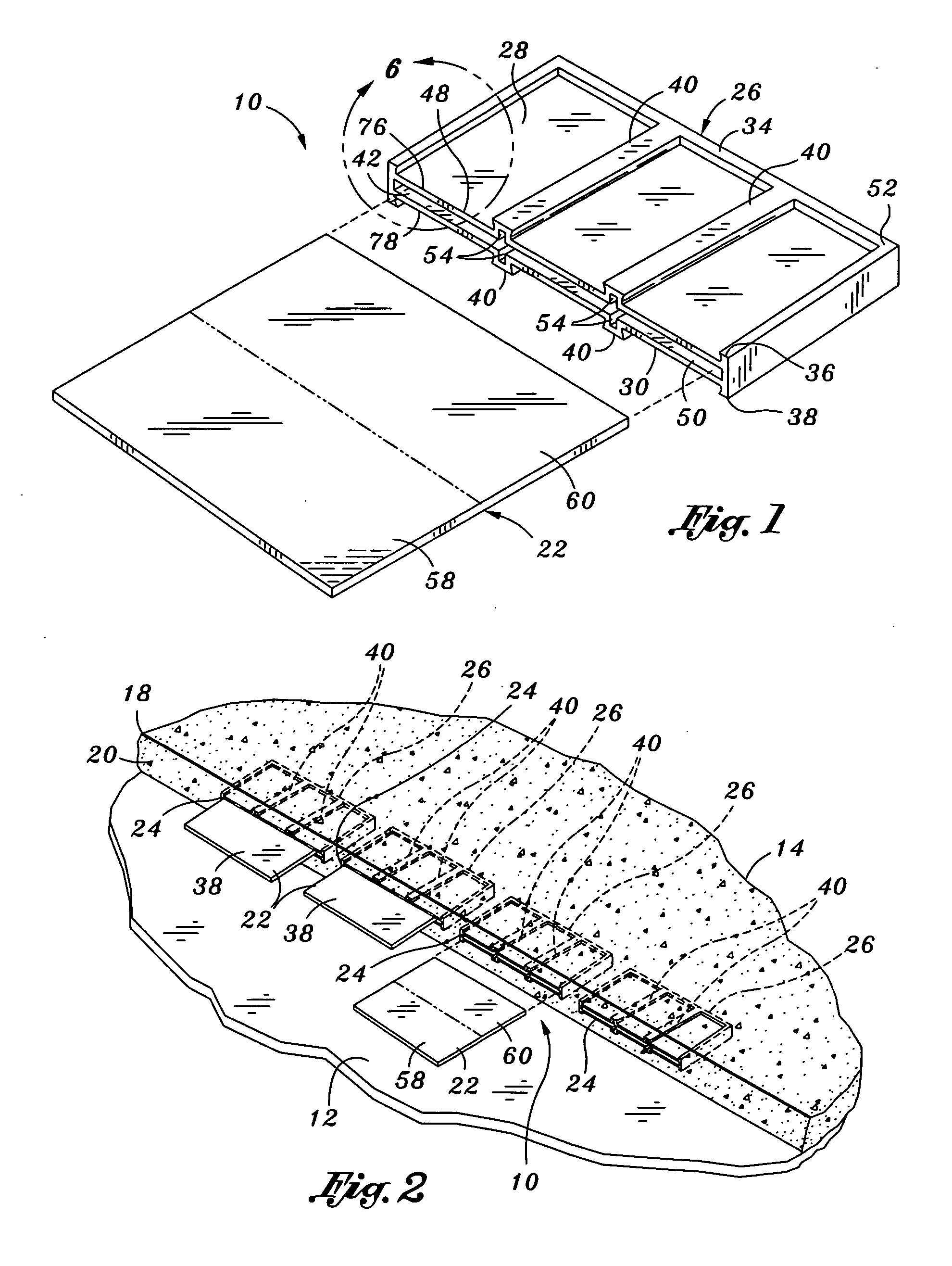
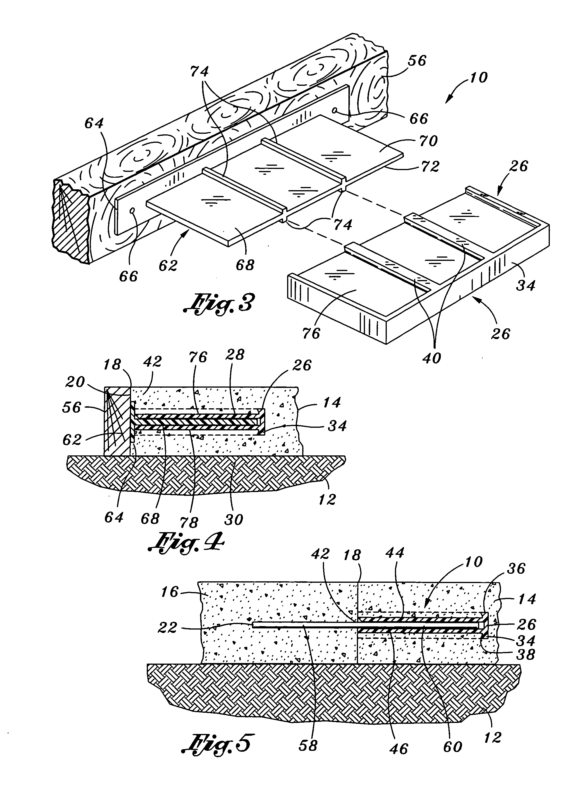
[0038] Referring now to the drawings wherein the showings are for purposes of illustrating the present invention and not for purposes of limiting the same, FIG. 1 illustrates a dowel plate 22 and corresponding pocket former 26 of the disc dowel system 10 of the present invention. The disc dowel system 10 is installed at a pour joint 18 between a first concrete pour 14 and a second concrete pour 16 disposed above a subgrade or a substrate 12, as can be seen in FIG. 5. The substrate 12 may be soil underlying the first and second pours 14, 16. Alternatively, the substrate 12 may be a metal decking or other surface that is adapted to support concrete.

[0039] As can be seen in FIGS. 1 and 2, the disc dowel system 10 is comprised of the dowel plate 22 and the pocket former 26. In FIG. 2, a series of the pocket formers 26 are shown encapsulated in the first pour 14 prior to pouring of the second pour 16. The disc dowel system 10 may further include a positioner bracket 62 for positioning t...


PUM


Abstract

A disc dowel system is interposed between adjacent first and second concrete pours defining a pour joint therebetween. The disc dowel system comprises a pocket former having a rib insert disposable therewithin for engaging the sides of a dowel plate. The pocket former has a vertical base flange with a pair of fastener-receiving bosses for securing the pocket former to a concrete form. The pocket former has a horizontally extending interior compartment with an open straight side that is aligned with the pour joint and is positioned within the first pour. The dowel plate has an orthogonal shape with an embedded portion and a slidable portion. The embedded portion is rigidly encapsulated within the second pour. The slidable portion is slidably disposed within the pocket former such that the dowel plate permits relative horizontal movement of the first and second pours while restricting relative vertical movement thereof.

Description

CROSS-REFERENCE TO RELATED APPLICATIONS [0001] This application is a continuation-in-part application of co-pending U.S. application Ser. No. 11 / 103,863, entitled DISK PLATE CONCRETE DOWEL SYSTEM, filed on Apr. 12, 2005, which is a continuation of U.S. application Ser. No. 10 / 640,556, filed Aug. 13, 2003, now U.S. Pat. No. 6,926,463, the entire contents of each being expressly incorporated by reference herein. This application is also related to co-pending U.S. application Ser. No. 11 / 360,828, filed on Feb. 23, 2006, and to co-pending U.S. application Ser. No. 11 / 400,006, filed on Apr. 7, 2006, both of which are entitled PLATE CONCRETE DOWEL SYSTEM, the entire contents of both being expressly incorporated by reference herein.STATEMENT RE: FEDERALLY SPONSORED RESEARCH / DEVELOPMENT [0002] (Not Applicable) BACKGROUND [0003] The present invention relates generally to concrete forming equipment and, more particularly, to a uniquely configured disc dowel system that is specifically adapted...

Claims


Application Information

Patent Timeline
IPC IPC(8): E01C11/14
CPCE01C19/504E01C11/14
Inventor SHAW, LEE A.SHAW, RONALD D.
Owner SHAW & SONS
Why Eureka
Try Eureka