
Carrier for a fastening element to be fabricated and a method for production thereof, particularly as an orthodontic bracket

a technology of fastening elements and brackets, which is applied in the field of orthodontic brackets, can solve the problems of not taking into account individual conditions of the attachment area on the tooth, orthodontic fastening devices have a standard geometry which cannot be adjusted to the geometry of the tooth surface, etc., and achieves the effect of easy removal from the tooth

Inactive Publication Date: 2006-12-07
SIRONA DENTAL SYSTEMS
View PDF12 Cites 67 Cited by
  • Summary
  • Abstract
  • Description
  • Claims
  • Application Information

AI Technical Summary

Benefits of technology

[0013] The fastening element is advantageously connected to the carrier piece at a lateral region between its front and rear side. This makes possible easy accessibility of the tools of the finishing machine to the fastening element.
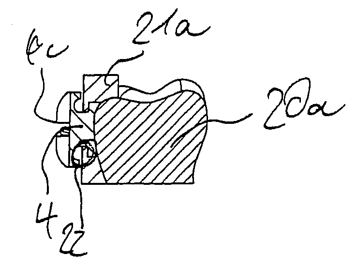
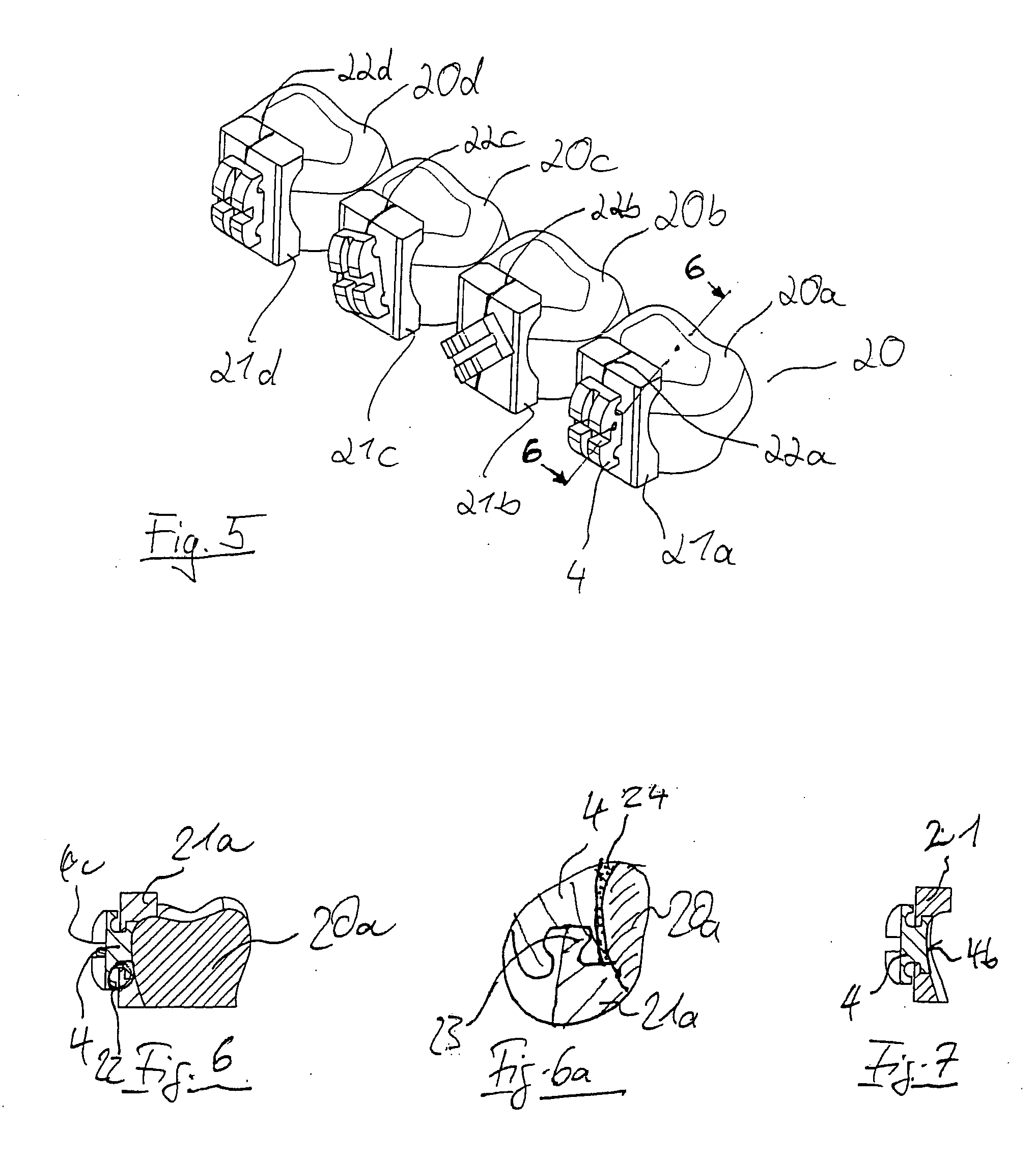
[0035] It is of special advantage if the attachment area is set back relative to the auxiliary positioning part by an offset from the surface onto which the fastening element is to be attached. This allows enough space for application of a suitable adhesive whereby the set-back is chosen to correspond to the desired thickness of the adhesive.

Problems solved by technology

It is of disadvantage in this case that the individual conditions of the attachment area on the tooth are not taken into consideration even with the individual design of the slot and the holding piece.
The disadvantage of the aforementioned orthodontic methods and devices is the fact that the orthodontic fastening devices have a standard geometry which cannot be adjusted to the geometry of the tooth surface.

Method used


Image

  • Carrier for a fastening element to be fabricated and a method for production thereof, particularly as an orthodontic bracket
  • Carrier for a fastening element to be fabricated and a method for production thereof, particularly as an orthodontic bracket
  • Carrier for a fastening element to be fabricated and a method for production thereof, particularly as an orthodontic bracket

Examples


Embodiment Construction

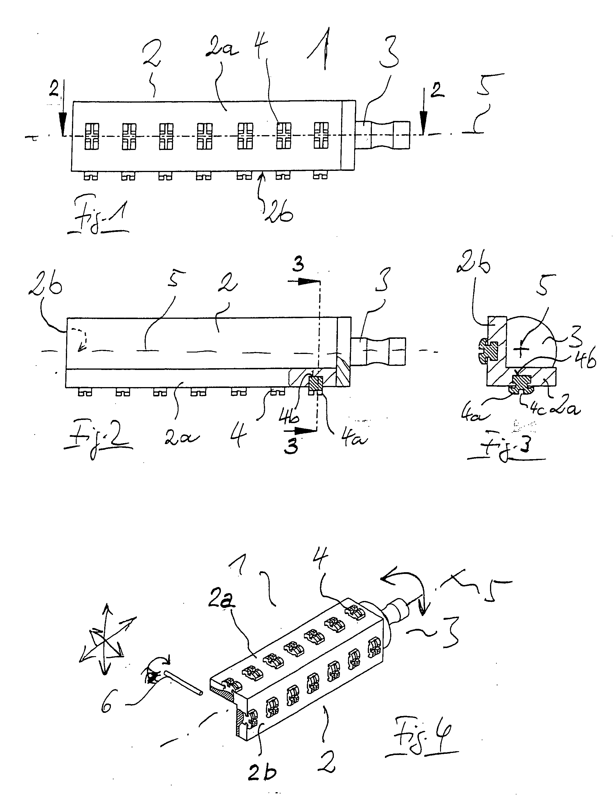
[0053]FIG. 1 illustrates a carrier 1 comprising a carrier piece 2 and a holding part 3 for attachment to a non-illustrated receiving part of a finishing machine. A plurality of fastening elements 4 are arranged in the carrier piece 2. The fastening elements 4 are juxtaposed along a longitudinal axis 5 of the carrier.

[0054]FIG. 2 shows a sectional view along line 2-2 in FIG. 1. Portions of the fastening elements 4 project past the carrier piece 2. It can be clearly seen in conjunction with FIG. 3 that the carrier piece 2 consists of two sections 2a and 2b which are one piece and which form an angle of approximately 90 degrees. Section 2a and section 2b are accessible from the rear, which means the side facing the longitudinal axis 5, for finishing with a fabrication tool.

[0055] It can be seen furthermore that one side of each fastening element 4 facing away from the carrier piece 2 is provided with a holding piece 4a whereby the opposite side, which is an attachment area 4b, is com...


PUM

PropertyMeasurementUnit
angleaaaaaaaaaa
angleaaaaaaaaaa
distanceaaaaaaaaaa

Abstract

A carrier for at least one fastening element (4) to be fabricated having an attachment area whereby the carrier is provided with a holding piece (3) for attachment in a receiving part of a finishing machine and whereby the carrier includes a carrier piece (2) for the fastening element (4) and the carrier piece (2) is embedded at least partially in the carrier piece (2) in a manner so that the attachment area (4b) of the fastening element (4) can be fabricated. A method for producing a fastening element (4) to be finished and to be attached to an individual surface whereby the contour of the attachment area is defined with the aid of data of the surface onto which the fastening element (4) is to be attached and whereby a pre-shaped, not yet individualized fastening element (4) is formed by removal of material to produce the specific contour. Furthermore, an auxiliary positioning part (21) is provided with a contour that is continued by the contour of the attachment area, which is also defined by the surface onto which the fastening element (4) is to be attached.

Description

CROSS-REFERENCE RELATED APPLICATION [0001] This application is related to U.S. Provisional Application No. 60 / 755,085, filed Jan. 3, 2006, the priority of which is hereby claimed, and it claims priority of German Patent Application No. 10 2005 025 5574, filed Jun. 1, 2005.FIELD OF THE INVENTION [0002] The invention relates to a carrier for a fastening element to be fabricated, a fastening element and a method for the production of this fastening element, particularly as an orthodontic bracket. The PRIOR ART [0003] DE 693 27 661 T2 discloses the production of an orthodontic bracket whereby a slot for an arch wire is cut into a bracket blank. Cutting of the slot is performed according to individual requirements after a corresponding computation by means of a program. A holding piece constructed individually for each tooth is fabricated for the individually constructed bracket made from round plastic disks. The radius of the cutter of the fabricating tool is thereby taken into consider...

Claims


Application Information

Patent Timeline
Patent Type & Authority Applications(United States)
IPC IPC(8): A61C3/00A61C3/04
CPCA61C7/12A61C7/14A61C7/146Y10T29/49567A61C7/16A61C7/20Y10T29/49568A61C2202/00
Inventor FORNOFF, PETER
Owner SIRONA DENTAL SYSTEMS
Learn More