Eureka AIR delivers breakthrough ideas for toughest innovation challenges, trusted by R&D personnel around the world.

Clip machine comprising a closure lever and a process for the production of a closure lever

Inactive Publication Date: 2006-12-07
POLY CLIP SYST
View PDF6 Cites 0 Cited by
  • Summary
  • Abstract
  • Description
  • Claims
  • Application Information

AI Technical Summary

Benefits of technology

[0010] The considerably lower specific density of the fiber-reinforced plastic composite, particularly when using a carbon fiber-reinforced plastic (CFRP) means that the mass moment of inertia of the closure lever can be reduced by about 30% at least while retaining and in part even when improving the mechanical load-bearing capability. This means that all drive elements are smaller and lighter in dimension to a corresponding degree and the costs of the overall clip machine can be reduced or the working speed of the clip machine can be increased with the dimensioning of the drive elements remaining the same. The use of a FRPC material, because of different resonance properties, also means that the abrupt closure movement of the closure tools exper

Problems solved by technology

Besides the above-indicated disadvantages that also had the consequence that the bearing element, the receiving element and the force application element as well as other functional elements such as cams or running surfaces and mounting points can only be produced with the necessary precision on the cast

Method used


Image

  • Clip machine comprising a closure lever and a process for the production of a closure lever
  • Clip machine comprising a closure lever and a process for the production of a closure lever
  • Clip machine comprising a closure lever and a process for the production of a closure lever

Examples


Example

DETAILED DESCRIPTION OF THE DRAWINGS

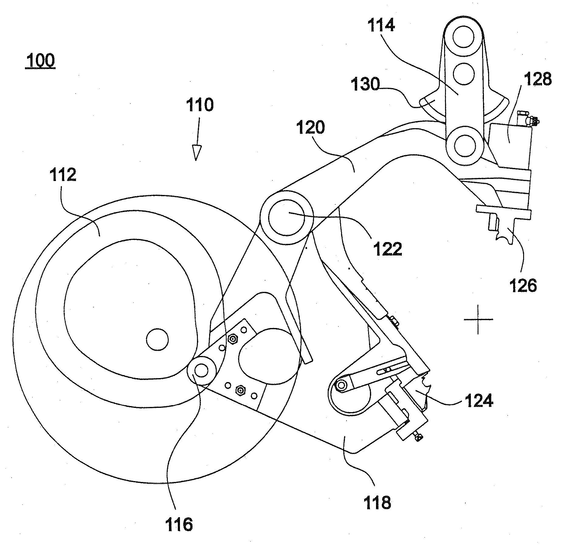
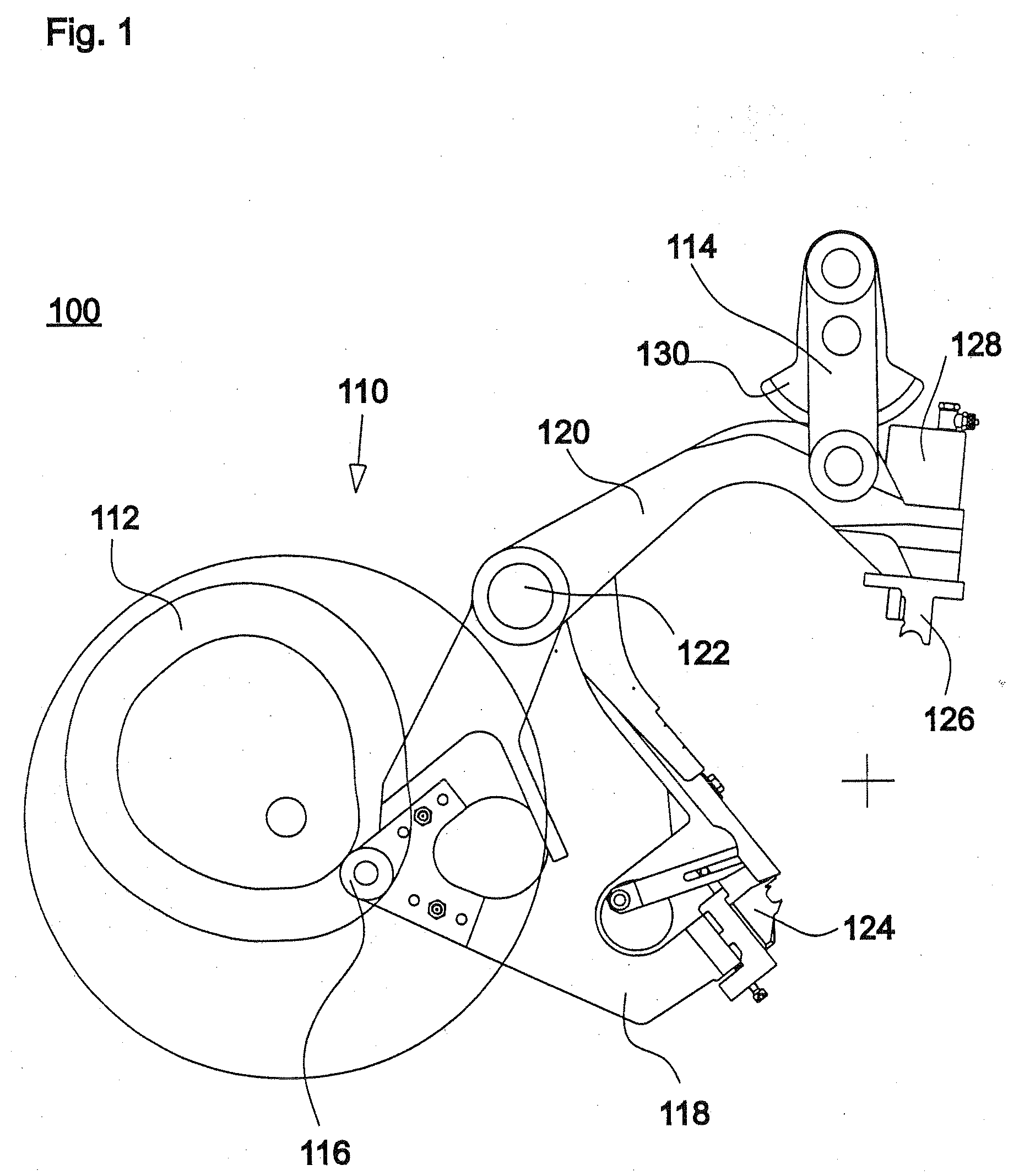
[0016] The embodiment shown in FIG. 1 of the clip machine 100 according to the invention has a clip machine drive 110 with a cam disk 112, from which the movement is taken for a lower closure lever 118 by means of a cam roller 116. In addition the clip machine has a further clip machine drive with a crank 130, from which the movement for an upper closure lever 120 is taken by means of a lever arm 114. In the illustrated embodiment, the two closure levers 118, 120 are mounted pivotably about the same pivot axis 122. At its end remote from the pivot axis 122 the lower clip lever 118 carries a first closure tool 124 which is a female die in the illustrated embodiment. At the same spacing relative to the pivot axis 122 the upper clip lever 120, at its end opposite to the pivot axis 122, carries a second closure tool 126 which is here a male die.

[0017] The lower closure lever 118 pivots upwardly about the common pivot axis 122, driven by way of a low...


PUM


Abstract

The invention concerns a clip machine comprising at least one closure lever which has a bearing element defining a pivot axis, a receiving element for at least one first closure tool and a force application element for connection to a drive element, wherein the closure lever is mounted pivotably between an open position and a closed position, in which closed position the first closure tool can be brought into engagement with a second closure tool to close a clip. In that respect the closure lever is produced at least partially from a fiber-reinforced plastic composite (FRPC).

Description

[0001] This patent application claims priority to German patent application DE 10 2005 025 173.0-27, filed Jun. 1, 2005, hereby incorporated by reference. TECHNICAL FIELD [0002] The present invention relates to a clip machine, and in particular to a clip machine comprising at least one closure lever which has a bearing element defining a pivot axis, a receiving element for a first closure tool and a force application element for connection to a drive element, wherein the closure lever is mounted pivotably between an open position and a closed position, in which closed position the first closure tool can be brought into engagement with a second closure tool to close a clip. The invention further concerns a process for the production of such a clip lever as well as the use of such a clip lever in a clip machine for portioning sausages. BACKGROUND OF THE INVENTION [0003] Clip machines of the specified kind are used typically for portioning and closing sausages with a liquid to a firm p...

Claims


Application Information

Patent Timeline
IPC IPC(8): A22C11/12B65B51/05
CPCB65B51/04
Inventor EBERT, DETLEF
Owner POLY CLIP SYST
Why Eureka
Eureka Blog
Learn More