Leaflike shaft of a hip-joint prosthesis for anchoring in the femur

a hip joint and prosthesis technology, applied in the field of leglike shaft of a hip joint prosthesis for anchoring in the femur, can solve the problems of poor growth of bone tissue, and achieve the effect of long-term, firm retention of the leglike sha

Inactive Publication Date: 2006-12-07
SMITH & NEPHEW ORTHOPAEDICS
View PDF31 Cites 11 Cited by
  • Summary
  • Abstract
  • Description
  • Claims
  • Application Information

AI Technical Summary

Benefits of technology

The invention is about a new design for a femur-anchoring section of a leaf-like shaft that helps to securely hold the prosthesis in place over the long term. The design encourages the growth of spongy bone tissue, which helps to ensure a firm attachment to the femur.

Problems solved by technology

The technical problem addressed in this patent text is how to improve the fusion of shafts to bony substances in the body, particularly in cases where the shaft is designed with smooth surfaces and the tissue growth is poor.

Method used


Image

  • Leaflike shaft of a hip-joint prosthesis for anchoring in the femur
  • Leaflike shaft of a hip-joint prosthesis for anchoring in the femur
  • Leaflike shaft of a hip-joint prosthesis for anchoring in the femur

Examples


Embodiment Construction

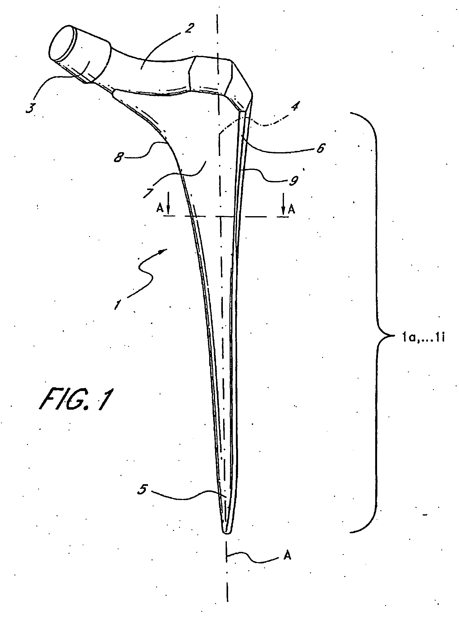
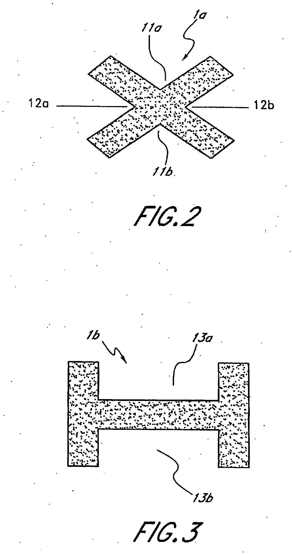
[0035]FIG. 1 shows, in perspective, a leaf-like shaft 1 of a hip-joint prosthesis for anchoring in the femur. The exemplary embodiment shown here comprises an anchoring section 1a, . . . 1i (see FIGS. 2 to 10), which expands conically on all sides from a distal end 5 to the proximal region, where on the medial side it merges with a continuously curving arch 8. This arch 8 is continuous with a prosthesis neck 2, onto which is set a conically tapering peg 3 which receives a spherical joint head. The prosthesis neck axis intersects the central long axis (not shown in FIG. 1) of the shaft and the anchoring section 1A . . . 1i at an angle that corresponds substantially to the angle between the neck and axis of the femur in a natural hip joint.

[0036] Laterally in the proximal region of the shaft 1 a trochanter wing 4 is formed, which is laterally delimited by a side surface 9. The transition between the lateral surface and the posterior or anterior surface is defined by a slanted edge 6 ...


PUM


Abstract

The present invention relates in certain embodiments to components of a hip-joint prosthesis. More particularly, embodiments of the invention relate to a leaf-like femoral shaft for use as part of a hip-joint prosthesis, and instruments (e.g., a rasp) and methods for implanting the shaft. The shaft includes an anchoring section extending between a proximal region and a distal end of the shaft. The shaft has a cross-sectional contour that defines a lateral side, a medial side, an anterior side and a posterior side. A corresponding rasp is preferably provided for each femoral shaft. The rasp is inserted into the femur to form a cavity having generally the same configuration as the rasp. The shaft is configured to be over-dimensioned in at least one of the anterior-posterior direction and medial-lateral direction relative to the rasped femur cavity. In one embodiment, the distance between diagonally opposite corner junctions of the shaft is substantially equal to the distance between corresponding diagonally opposite corner junctions of the femur cavity, so as to inhibit excess stress on the corticalis.

Description


Claims


Application Information

Patent Timeline
Owner SMITH & NEPHEW ORTHOPAEDICS
Why Eureka
Try Eureka