Red-eye correction method and apparatus with user-adjustable threshold

a technology of red eye and threshold, applied in the field of digital photography, can solve the problems of false positives, red eyes, and false positives, and achieve the effect of correcting erroneously and red eyes

Inactive Publication Date: 2006-12-14
HEWLETT PACKARD DEV CO LP
View PDF2 Cites 37 Cited by
  • Summary
  • Abstract
  • Description
  • Claims
  • Application Information

AI Technical Summary

Problems solved by technology

A pervasive problem in flash photography is the “red-eye effect,” in which an on-camera flash reflects off the back of the eyes of a subject, causing the eyes to appear red.
The problem is so common that many digital photo-editing applications incl

Method used


Image

  • Red-eye correction method and apparatus with user-adjustable threshold
  • Red-eye correction method and apparatus with user-adjustable threshold
  • Red-eye correction method and apparatus with user-adjustable threshold

Examples


Embodiment Construction

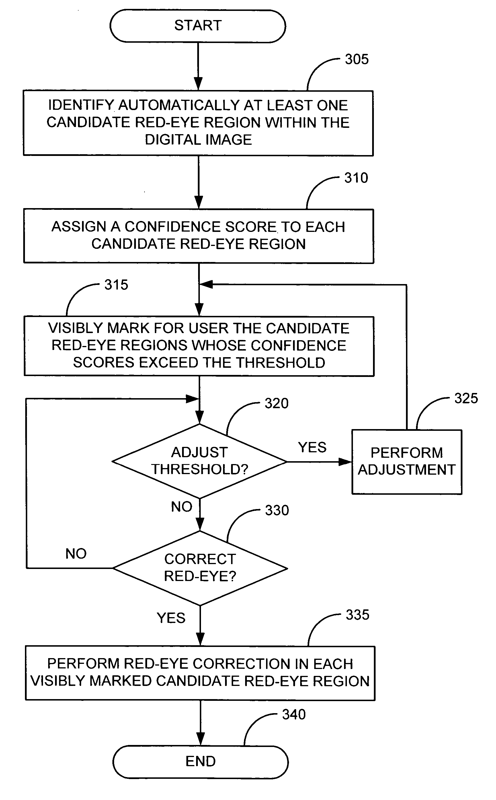
[0014] Red-eye correction may be improved by allowing a user to adjust the threshold dynamically. After the digital image has been analyzed to identify candidate red-eye regions, the digital image may be presented to the user, and the candidate red-eye regions whose figures of merit exceed a predetermined initial threshold may be visibly marked within the digital image. As the user adjusts the threshold dynamically, more or fewer candidate red-eye regions may be visibly marked in accordance with the adjusted threshold.

[0015] One advantage of this approach is that the predetermined initial threshold may be set less sensitively at the outset to eliminate more false positives (candidate red-eye regions that do not contain a genuine “red eye”). If the algorithm misses genuine “red eyes,” the user may easily compensate by adjusting the threshold to increase the sensitivity. In some cases (i.e., where all false positives have less favorable figures of merit than all of the genuine “red e...


PUM


Abstract

An electronic device that performs automatic red-eye correction on digital images includes a user-adjustable threshold, enabling the user to adjust the sensitivity of the automatic red-eye-correction algorithm dynamically while viewing marked candidate red-eye locations in a digital image. Such dynamic adjustment of the threshold facilitates the rejection of false positives while reducing the number of input gestures required of the user.

Description

FIELD OF THE INVENTION [0001] The present invention relates generally to digital photography and more specifically to user interfaces used in conjunction with the correction of red-eye effect in digital images. BACKGROUND OF THE INVENTION [0002] A pervasive problem in flash photography is the “red-eye effect,” in which an on-camera flash reflects off the back of the eyes of a subject, causing the eyes to appear red. The problem is so common that many digital photo-editing applications include automatic or manual red-eye correction. Some digital cameras are also capable of performing red-eye correction in the camera itself. [0003] Automatic red-eye correction algorithms typically analyze the digital image based on a number of different features and assign a figure of merit to each potential red-eye region. The figure of merit may represent the degree of confidence that a particular potential red-eye region is indeed a “red eye.” Red-eye correction is then performed on the potential r...

Claims


Application Information

Patent Timeline
IPC IPC(8): G06K9/40
CPCG06K9/0061G06T2207/30216G06T7/408G06T7/90G06V40/193
Inventor DALTON, DAN L.WHITMAN, CHRISTOPHER A.
Owner HEWLETT PACKARD DEV CO LP
Why Eureka
Try Eureka