
Insect trap

a technology for insect traps and insect bites, applied in the field of insect traps, can solve the problems of complex and expensive production, too costly to be disposable, and existing traps that require multi-step assembly processes

Inactive Publication Date: 2006-12-21
FARMA TECH INT CORP
View PDF11 Cites 29 Cited by
  • Summary
  • Abstract
  • Description
  • Claims
  • Application Information

AI Technical Summary

Benefits of technology

[0009] The interior space of the trap is provided with an insect attractant means, such as an attractant dispensing body comprising a thin wafer impregnated with an insect attractant formulation. Other types of attractant means could be used, such as attractant impregnated plugs, pastes, woven sheets or baskets that hold various lure formulations. However, an advantage of the trap is that it accommodates a thin self-supporting wafer without the aforementioned bulky plugs or baskets that require suspension means.
[0010] The trap includes a fold-over flap and a tear-strip that allows the trap to be folded upon itself after use. This action creates a trap enclosure in which the sticky surfaces face inwardly, so that the integrity of the insects captured thereon may be protected against damage during subsequent shipment and scientific evaluation.
[0011] The completed trap includes a connector means for engagement with an ambient structure. This allows the trap to be suspended from bushes, trees and other elevated structures which are located in areas of interest.

Problems solved by technology

Common problems with existing insect traps are that they are complicated and expensive to produce.
As such, they are too costly to be disposable.
Additionally, existing traps require multi-step assembly processes, even though they are initially formed from blank sheet materials.
The trap is too elaborate to be disposable, and would not be affordable for use in relation to large insect infestations.
However, they both require multiple folded panels to create interior chambers and unnecessary multi-layered grill panels.
While this device may be suitable for use in a backyard or garden, it would not be suitable for high-volume agricultural use because of its limited attractant surface area and frequent need for replacement of the adhesive / attractant sheets.

Method used


Image

  • Insect trap
  • Insect trap
  • Insect trap

Examples


Embodiment Construction

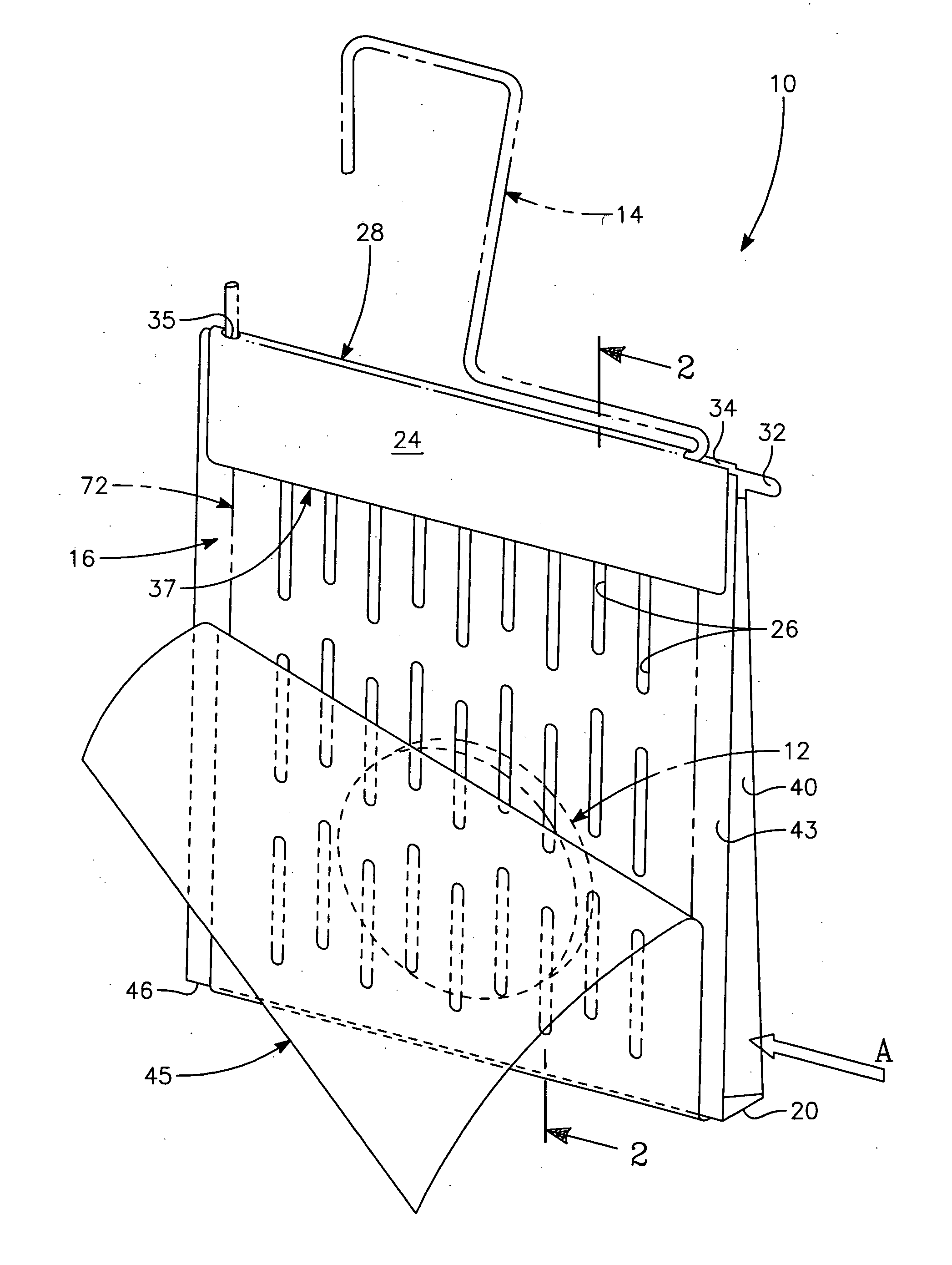
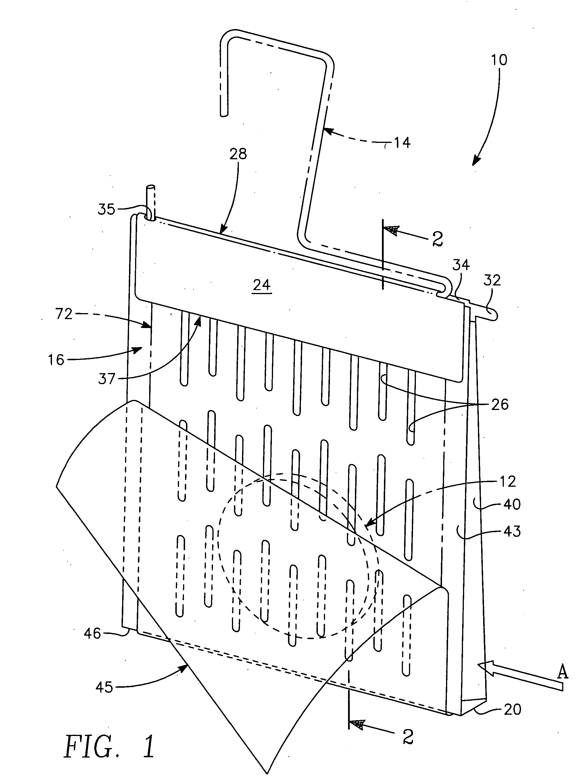
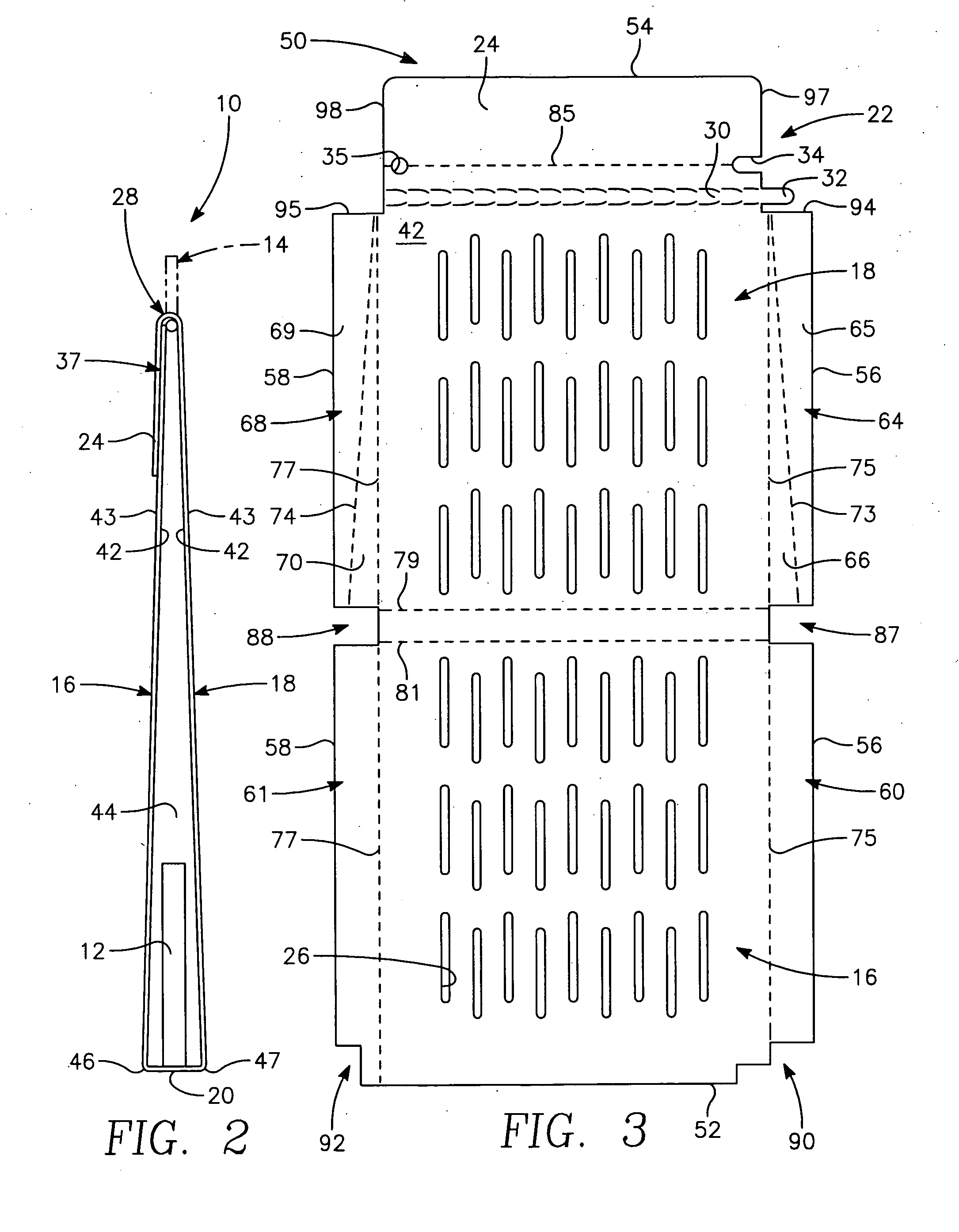
[0018] With particular attention to FIGS. 1 and 2, the overall insect trap is shown by reference 10. The trap comprises a housing having a first sidewall 16 and a second sidewall 18. The sidewalls extend upwardly from a base 20. The base includes hinge means that interconnect the sidewalls. As shown, the base comprises a base wall with a width defined by the space between front edge 46 and back edge 47. As discussed hereinafter, the front and back edges are defined by score lines which may also function as the aforesaid hinge means.

[0019] The first sidewall extends from front edge 46 a predetermined distance to a top edge 52. The second sidewall 18 extends from back edge 47 to a flap edge 54. At least the exterior surface 43 of first sidewall 16 is provided with an effective amount and distribution of insect adhesive 72. To maximize effectiveness, it is preferred that selected exterior surfaces of both sidewalls be provided with insect adhesive.

[0020] Both sidewalls include vertic...


PUM


Abstract

An insect trap is provided that is constructed of a precut sheet of foldable material. The sheet includes vent slots and adhesive layers over selected solid exterior areas. One or more base score lines extend across the mid-portion of the sheet to divide the sheet into first and second side walls. A flap score line extends across the upper sheet width to define a flap section and lateral score lines extend along the longitudinal extent of the sheet inward from the sheet opposing lateral edges, to define end wall parts. The trap is assembled by folding inwardly the end wall parts and rotating together the first and second side walls about the base score lines. The side walls are held together by rotating the flap section about the flap score line and securing it to corresponding upper portions of the adhesive layers.

Description

BACKGROUND OF THE INVENTION [0001] 1. Field of Invention [0002] The present invention relates to portable insect traps. In particular, the invention concerns disposable insect traps for outdoor use, utilizing an adhesive insect entrapment means on a disposable housing with an attractant lure. [0003] 2. Description of Related Art [0004] Common problems with existing insect traps are that they are complicated and expensive to produce. As such, they are too costly to be disposable. Additionally, existing traps require multi-step assembly processes, even though they are initially formed from blank sheet materials. [0005] For example, U.S. Pat. No. 6,516,558 describes an insect trap that includes an elaborate roof structure having a significant ridge construction produced from sheet materials. The ridge construction includes openings for insertion of roof-locking tabs. The roof is supported by end flaps having additional tabs which extend into base seam slots for additionally supporting ...

Claims


Application Information

Patent Timeline
IPC IPC(8): A01M1/14
CPCA01M1/14A01M1/02
Inventor CHAMBERS, DERRELL L.ALVARADO, RICHARDKNAPP, JOHN D.
Owner FARMA TECH INT CORP
Learn More