Vehicle braking control assistance system and method

a technology of vehicle braking and assistance system, which is applied in the direction of process and machine control, instruments, navigation instruments, etc., can solve the problems of braking based solely on experiential judgment of the driver, rarely occurring full braking, and not achieving the expected deceleration effect of braking

Inactive Publication Date: 2006-12-28
AISIN AW CO LTD
View PDF12 Cites 56 Cited by
  • Summary
  • Abstract
  • Description
  • Claims
  • Application Information

AI Technical Summary

Benefits of technology

[0009] Accordingly, it is an object of the present invention to provide a vehicle braking control assistance device and a vehicle braking control assistance method, for enabling the driver to appropriately determine excessive or insufficient current braking force, as compared to an ideal braking force, and to make an appropriate change in force on the brake pedal.
[0013] Accordingly, the driver of the vehicle can know the difference between the ideal brake pedal force and current brake pedal force, so that the driver can adjust the current brake pedal force to more closely approximate the ideal brake force.
[0019] Accordingly, the driver of the vehicle is informed of both the relationship between the ideal vehicle speed and the current vehicle speed, and the relationship between the ideal vehicle speed and a future predicted vehicle speed based on the current braking force and is thereby forewarned of how the vehicle speed will change based on the current braking force. Accordingly, the driver can adjust the current vehicle speed to approximate the ideal vehicle speed.
[0020] Also, the notification information preferably further includes information indicating the position of a predicted deceleration point at which the target vehicle speed will be reached by deceleration with the current braking force. Accordingly, the driver of the vehicle can know the location for the target vehicle speed relative to the deceleration target point, with deceleration in accordance with the current braking force, so that the brake application can be adjusted such that the target vehicle speed is reached at the deceleration target point.
[0033] In this third aspect of the invention, the driver of the vehicle, when decelerating, can be made aware of the relationship the current braking force in comparison with the range for the ideal braking force, and can thereby determine whether the current braking force is excessive or insufficient as compared to the range for ideal braking force. Accordingly, the driver can adjust pressure on the brake pedal to bring the current braking force within the range for the ideal braking force.

Problems solved by technology

However, full braking seldom occurs in actual driving and, also, the driver can spare little time to view a display when engaged in full braking.
However, braking based solely on experiential judgment of the driver may not result in the expected deceleration, due to differences in road surface conditions and road layouts and so forth.
In such cases, the driver needs to further change force on the brake pedal, which may result in awkward handling the vehicle, causing discomfort to other passengers, and placing an unnecessary load on the vehicle.

Method used


Image

  • Vehicle braking control assistance system and method
  • Vehicle braking control assistance system and method
  • Vehicle braking control assistance system and method

Examples


first embodiment

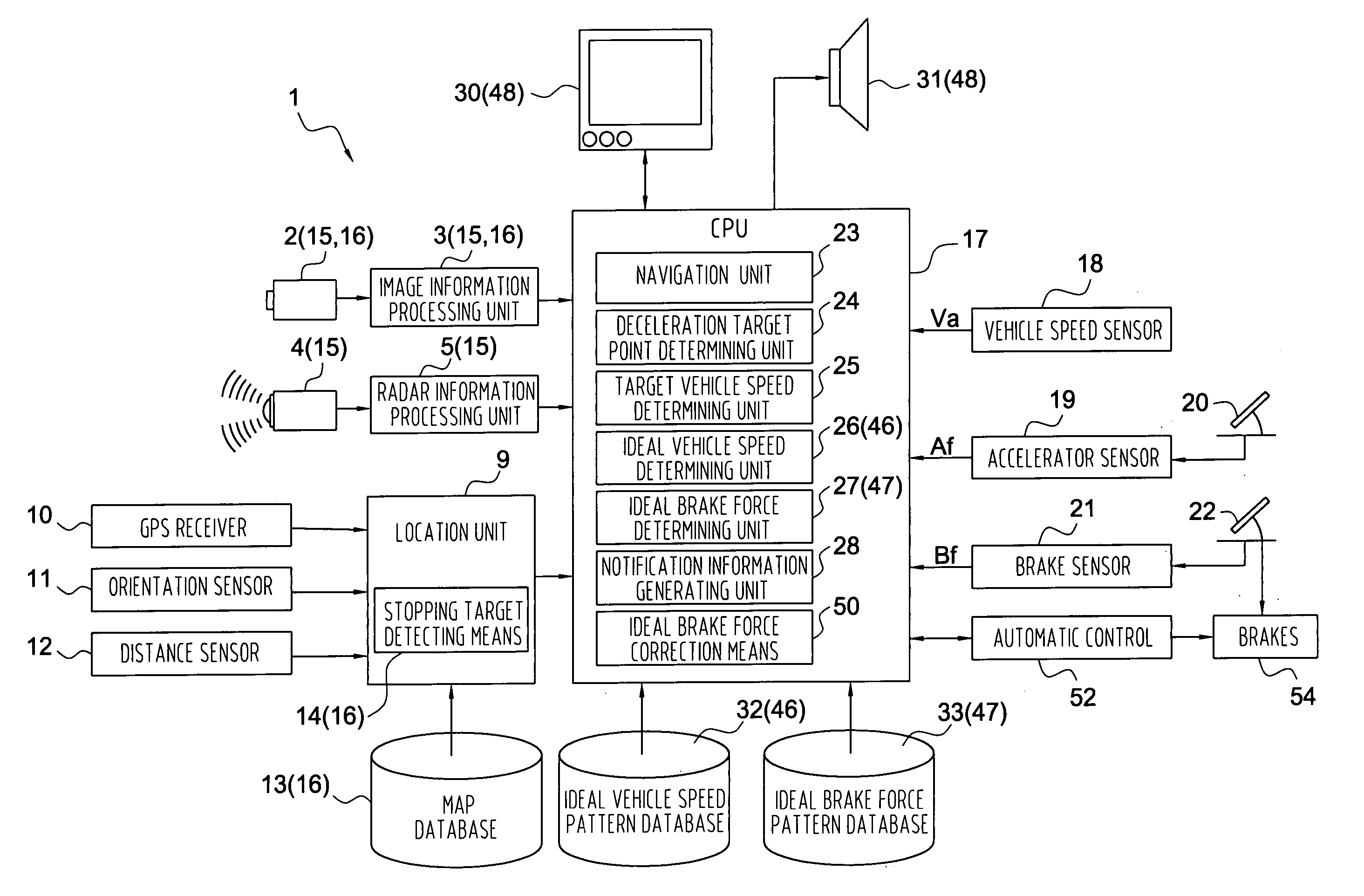
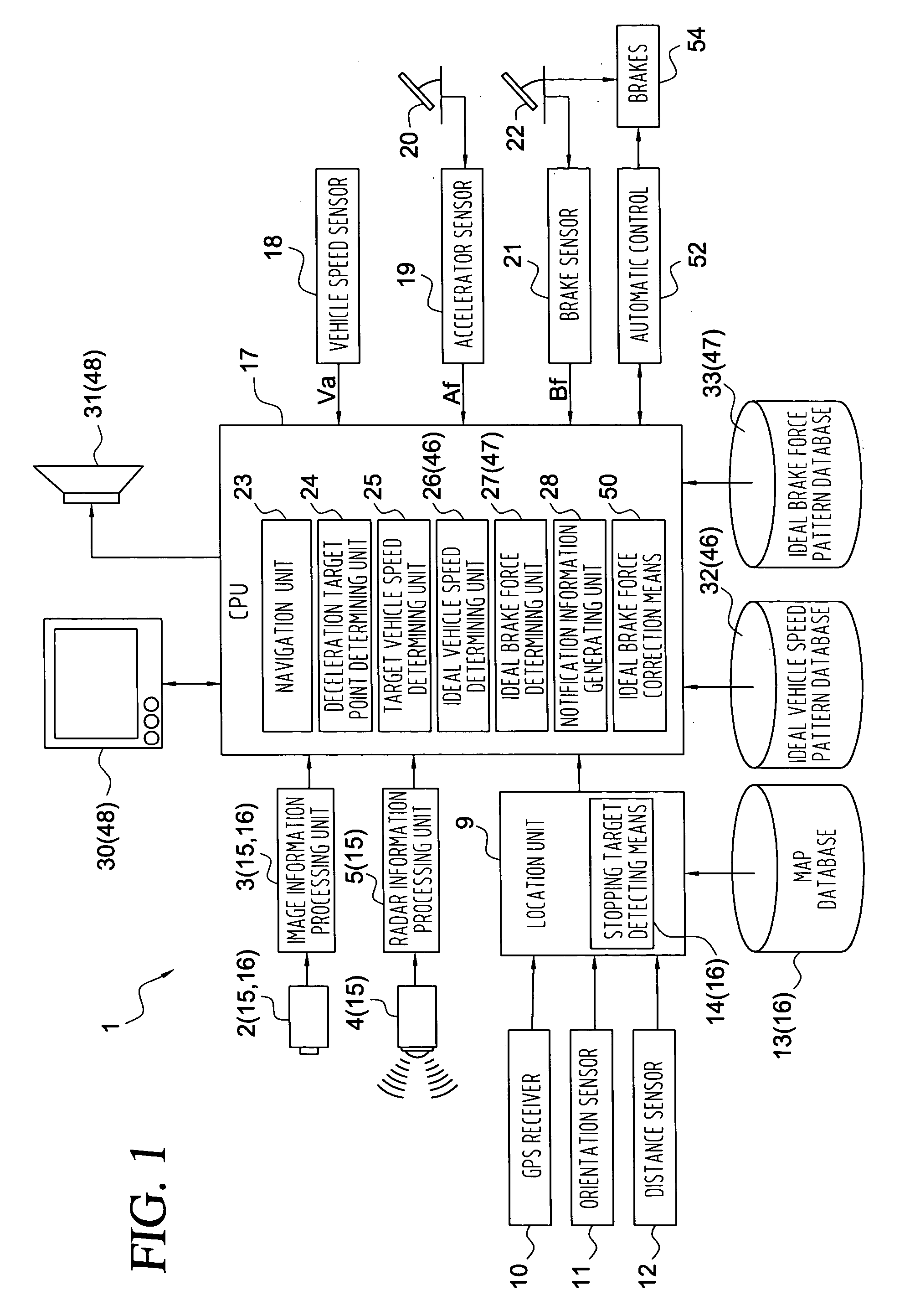
[0052] The vehicle control assistance device 1, according to a first embodiment of the present invention generates, when decelerating, information indicating the relationship between an ideal braking force and the current braking force and / or the relationship between ideal vehicle speed and the current vehicle speed, and communicates that information to the driver, thereby assisting in vehicle braking control. FIG. 1 shows the units of the vehicle braking control assistance device 1, which may be hardware or software (programs) or both, with an arithmetic processing unit such as a CPU serving as the central member, which units execute various routines for processing input data.

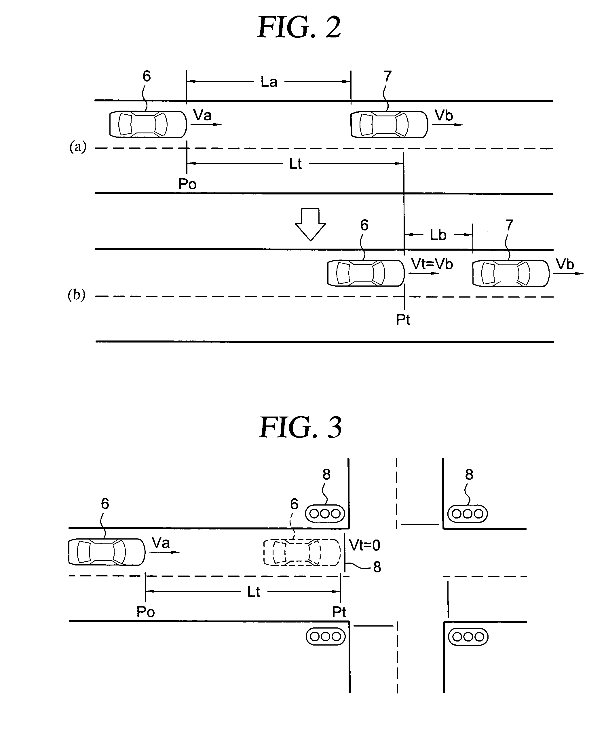
[0053] An image-taking device 2 is disposed in a driver's vehicle 6 for capturing images of the vicinity of the driver's vehicle 6, including preceding vehicles 7 ahead of the vehicle 6 in the direction of travel (see FIG. 2), stopping target features 8 (see FIG. 3), and so forth. Image-taking device 2 can be...

second embodiment

[0100] The vehicle brake control assistance device 1 according to the second embodiment differs from the previously described first embodiment with regard to the contents of the notification information generated by the notification information generating unit 28. Other components and features are the same as those of the first embodiment.

[0101]FIG. 12 illustrates one example of the notification information A according to the second embodiment. As shown in FIG. 12, the notification information A here is image information for display on the display device 30, and gives the relationship between the ideal vehicle speed and the current vehicle speed Va, and the relationship between the ideal vehicle speed and a predicted vehicle speed based on the current Bf. This notification information A further includes information indicating a future predicted deceleration point which determines the target vehicle speed Vt based on the assumption that deceleration will continue at the current brak...

fourth embodiment

[0107] Next, a fourth embodiment of a vehicle control assistance device 1 will be described. The vehicle control assistance device 1 of the fourth embodiment differs from the above embodiment in that only the ideal vehicle speed(s) to the deceleration target point Pt at the target vehicle speed is determined, without determining the ideal brake force up to the deceleration target point Pt, and information indicating the relationship between the ideal vehicle speed and the current vehicle speed Va is generated as the notification information A. Accordingly, the vehicle control assistance device 1 according to the fourth embodiment also differs from the above first embodiment in that there is no need to have an ideal brake force determining unit 27. Other components and features may be the same as those of the first embodiment.

[0108] In the fourth embodiment, the notification information generating unit 28 generates notification information A indicating the relationship between the i...


PUM


Abstract

A vehicle braking control assistance device includes: a speed detecting unit for detecting current vehicle speed; a brake force detecting unit for detecting the current braking force; a deceleration target point determining unit for determining a target point for deceleration control; a target vehicle speed determining unit for determining a target vehicle speed at the deceleration target point; an ideal brake force determining unit for determining an ideal brake force to be applied in continued movement to the deceleration target point with the target vehicle speed realized at the deceleration target point, based on the current vehicle speed, the deceleration target point and the target vehicle speed; a notification information generating unit for generating notification information indicating the relationship between the ideal brake force and the current brake force; and a notification unit for bringing the generated notification information to the attention of the driver.

Description

[0001] INCORPORATION BY REFERENCE [0002] The disclosure of Japanese Patent Application No. 2005-188204 filed on Jun. 28, 2005, including the specification, drawings and abstract thereof, is incorporated herein by reference in its entirety. BACKGROUND OF THE INVENTION [0003] 1. Field of the Invention [0004] The present invention relates to a vehicle braking control assistance system and to a vehicle braking control assistance method which assist the driver in vehicle control during braking by communicating to the driver information indicating the relationship between an ideal brake force and current brake pedal force and / or the relationship between ideal vehicle speed and current vehicle speed. [0005] 2. Description of the Related Art [0006] One technique for assisting in vehicle control during braking provides a display of the deceleration. For example, Japanese Unexamined Patent Application Publication No. 2004-101280 (pp 3-7, Fig. 10) discloses a technique utilizing a following ca...

Claims


Application Information

Patent Timeline
Patent Type & Authority Applications(United States)
IPC IPC(8): B60T8/66B60K31/00B60T8/00G01C21/00G01C21/26G08G1/16
CPCB60T7/22B60T2201/02B60W50/14B60W30/143B60W10/184
Inventor SHIBATA, YUMIYAMAMOTO, YUKIOMARUYAMA, KATSUYA
Owner AISIN AW CO LTD
Why Eureka
Try Eureka