
Multicolored lighting device and coordinate input device

Inactive Publication Date: 2006-12-28
ALPS ALPINE CO LTD
View PDF4 Cites 16 Cited by
  • Summary
  • Abstract
  • Description
  • Claims
  • Application Information

AI Technical Summary

Benefits of technology

[0008] A multicolored lighting device capable of illuminating an operation surface with high efficiency and high quality and a coordinate input device is provided.
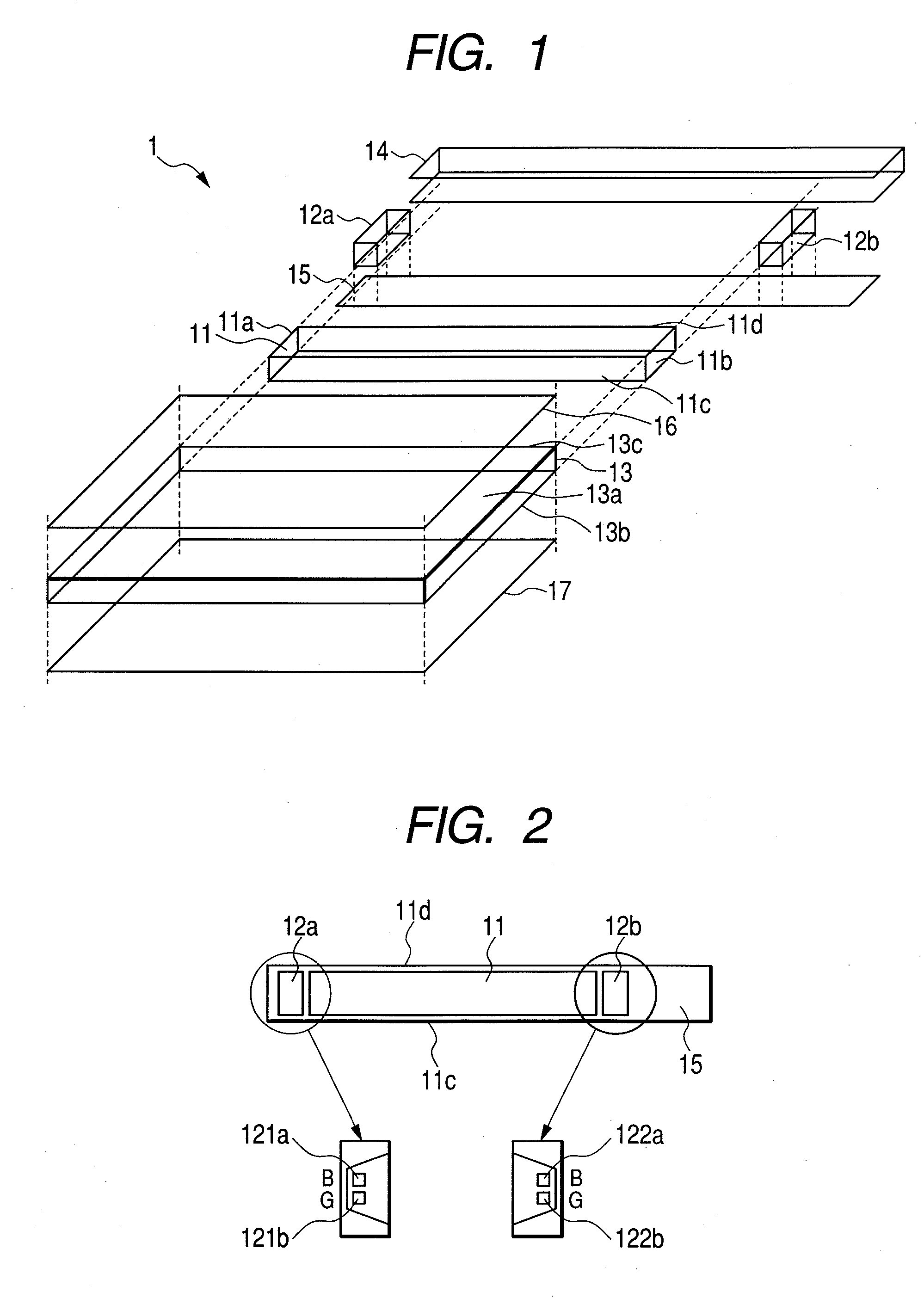
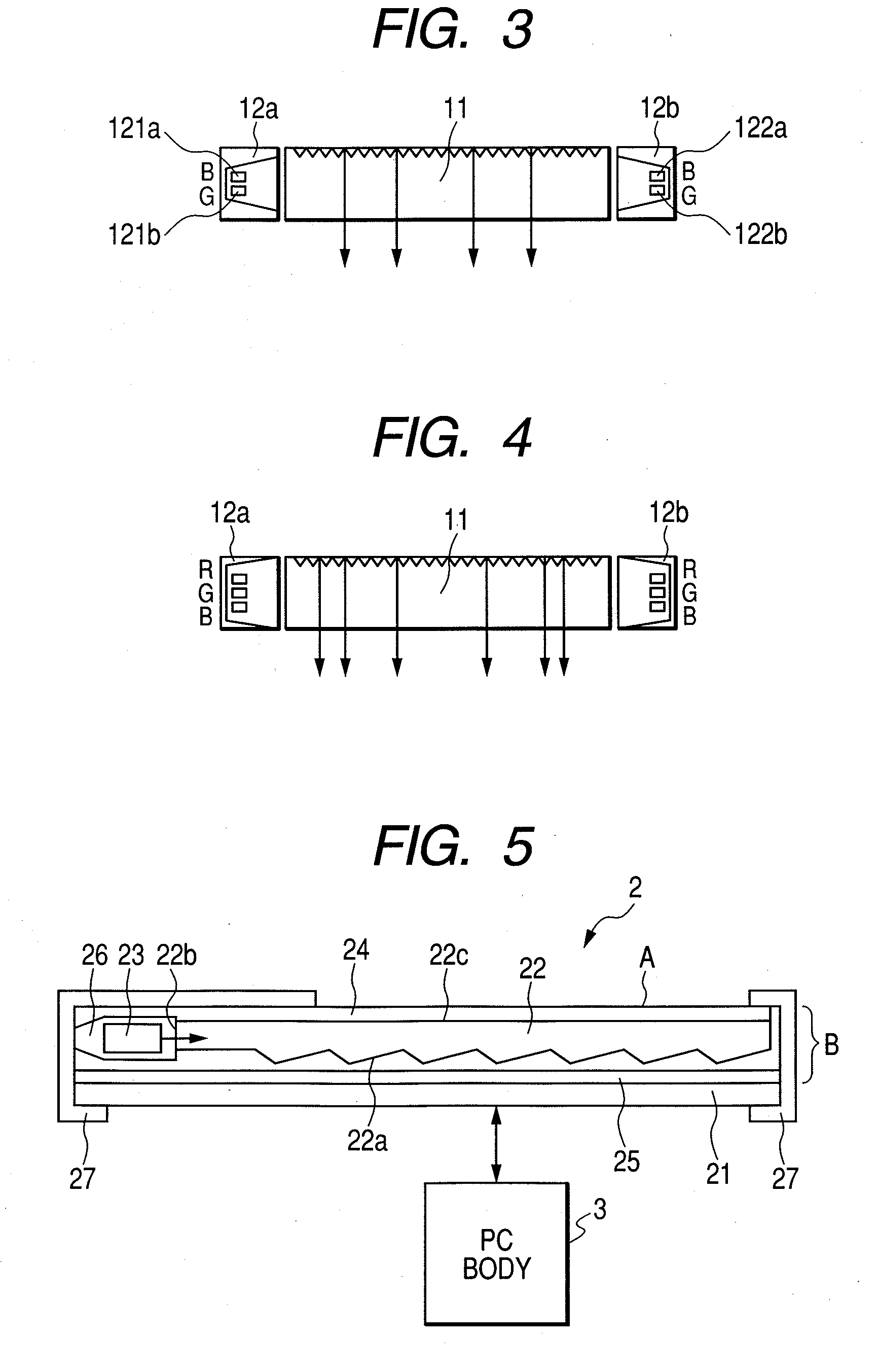
[0010] By this configuration, since the chromatic light sources in the multicolored light sources are symmetrically disposed with respect to the bar-shaped light guide, the illuminated light from the horizontally symmetrical multicolored light sources enters into the bar-shaped light guide having the horizontally symmetrical prism such that reflection of the light in the bar-shaped light guide and the light focusing balance (mixed-color light emitting property upon simultaneous lighting) are stabilized and light emitting quality is improved. As a result, it is possible to obtain good color tone of the illuminated light and to prevent brightness unevenness of the illuminated light.
[0013] Since a multicolored lighting device includes a bar-shaped light guide having a pair of first edges for receiving light and a side surface for emitting the light; a pair of multicolored light sources which is disposed in the vicinity of the pair of first edges; and a light guide having a pair of main surfaces that face each other and a second edge for receiving the light emitted from the side surface. The pair of multicolored light sources has a plurality of chromatic light sources. In the pair of multicolored light sources, the chromatic light sources having a same color are symmetrically disposed with respect to the bar-shaped light guide, an operation surface can be illuminated with high efficiency and high quality.

Problems solved by technology

Accordingly, since the light of the backlight is absorbed into the LCD or the sensor, sufficient light amount cannot be obtained.
In addition, since the sensor is made of a material having the optical transmission property, the cost increases.

Method used


Image

  • Multicolored lighting device and coordinate input device
  • Multicolored lighting device and coordinate input device
  • Multicolored lighting device and coordinate input device

Examples


Embodiment Construction

[0021] Hereinafter, embodiments will be described in detail with reference to the attached drawings.

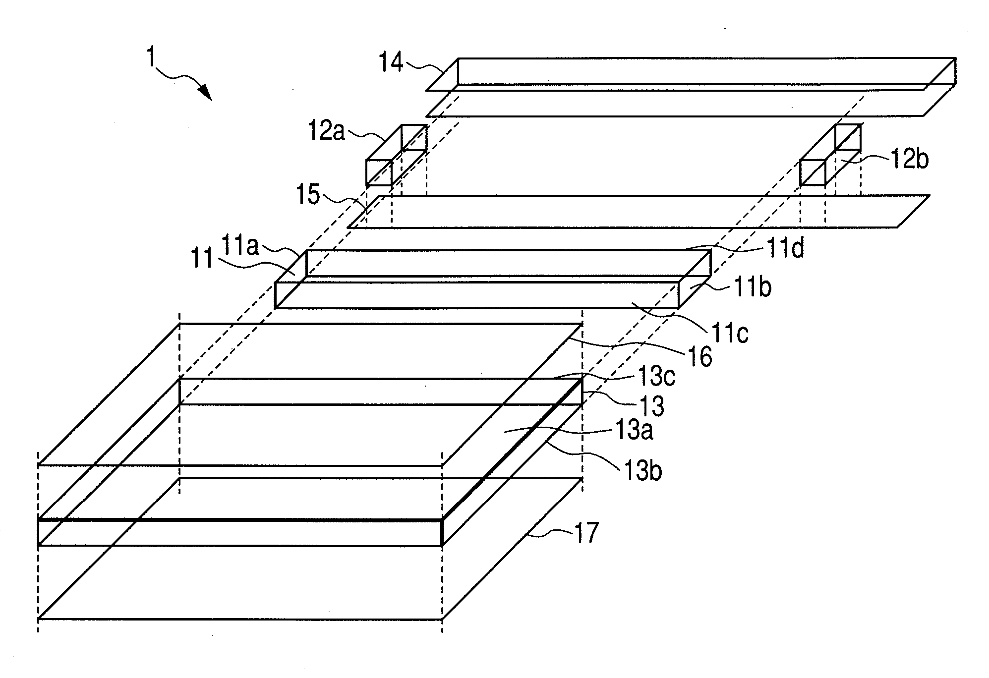
[0022]FIG. 1 is an exploded perspective view showing a multicolored lighting device. A multicolored lighting device 1 shown in FIG. 1 mainly includes a transparent bar-shaped light guide 11 having an elongate rectangular parallelepiped shape, multicolored light sources 12a and 12b for emitting light to an edge of the bar-shaped light guide 11, and a transparent light guide 13 for receiving the light from the bar-shaped light guide 11.

[0023] The bar-shaped light guide 11 includes a pair of edges 11a and 11b which is a first edge for receiving the light, a side surface 11c for emitting light which propagates in the bar-shaped light guide 11, and a side surface 11d facing the side surface 11c. The edges 11a and 11b face each other. The light from the multicolored light source 12a disposed in the vicinity of the edge 11a enters into the bar-shaped light guide 11 through the edge 11a, an...


PUM


Abstract

Provided is a multicolored lighting device capable of illuminating an operation surface with high efficiency and high quality and a coordinate input device. Themulticolored light sources are disposed in the vicinity of the edges of a bar-shaped light guide having a plurality of chromatic light sources. The chromatic light sources are symmetrically disposed with respect to the bar-shaped light guide.

Description

BACKGROUND [0001] 1. Field [0002] A multicolored lighting device and a coordinate input device is provided, and more particularly, a multicolored lighting device and a coordinate input device with high lighting quality. [0003] 2. Related Art [0004] Conventionally, in a portable computer terminal device such as a laptop computer, a coordinate input device called a touch pad is mounted. This touch pad is a pointing device for operating a cursor or a pointer displayed on a screen of the terminal device, similar to a mouse. When a user's finger or a pen tip comes in contact with an operation surface, a contact point is detected by a sensor and the cursor or the pointer is operated according to a coordinate value of the contact point or displacement of the coordinate value due to movement of the contact point. [0005] In such a coordinate input device, the sensor includes a sheet having an optical transmission property and a backlight-attached color liquid crystal display (LCD) panel is d...

Claims


Application Information

Patent Timeline
IPC IPC(8): G09G5/00
CPCG02B6/0038G02B6/0073G02B6/0068
Inventor NAGAKUBO, HIDEAKI
Owner ALPS ALPINE CO LTD
Learn More