Optical assembly with a lens magnification-adjusting function

Inactive Publication Date: 2006-12-28
BENQ CORP
View PDF9 Cites 4 Cited by
  • Summary
  • Abstract
  • Description
  • Claims
  • Application Information

AI Technical Summary

Problems solved by technology

Thus, the magnification-adjusting mechanism of the optical assembly 10 does not correspond to the habits of users such that it is inconvenient for users to operate the magnification-adjusting mechanism of the optical assembly 10.

Method used


Image

  • Optical assembly with a lens magnification-adjusting function
  • Optical assembly with a lens magnification-adjusting function
  • Optical assembly with a lens magnification-adjusting function

Examples


Embodiment Construction

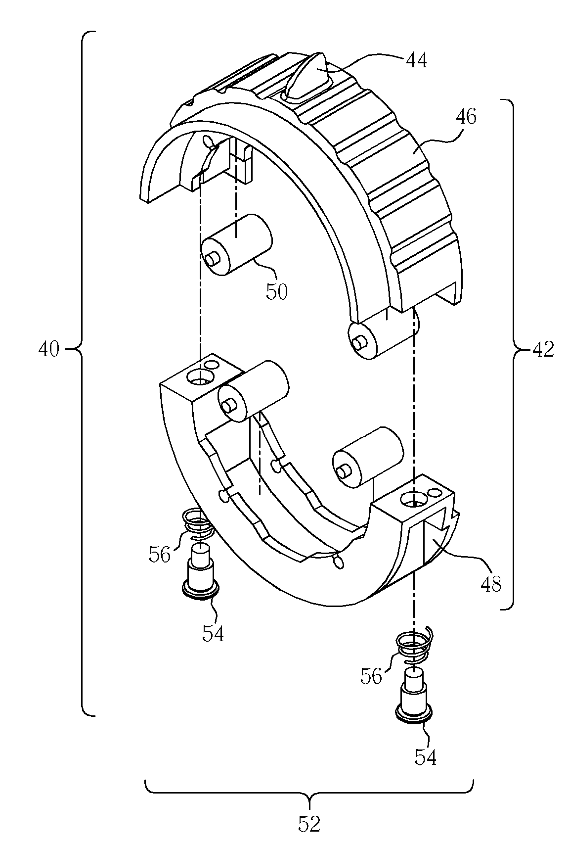
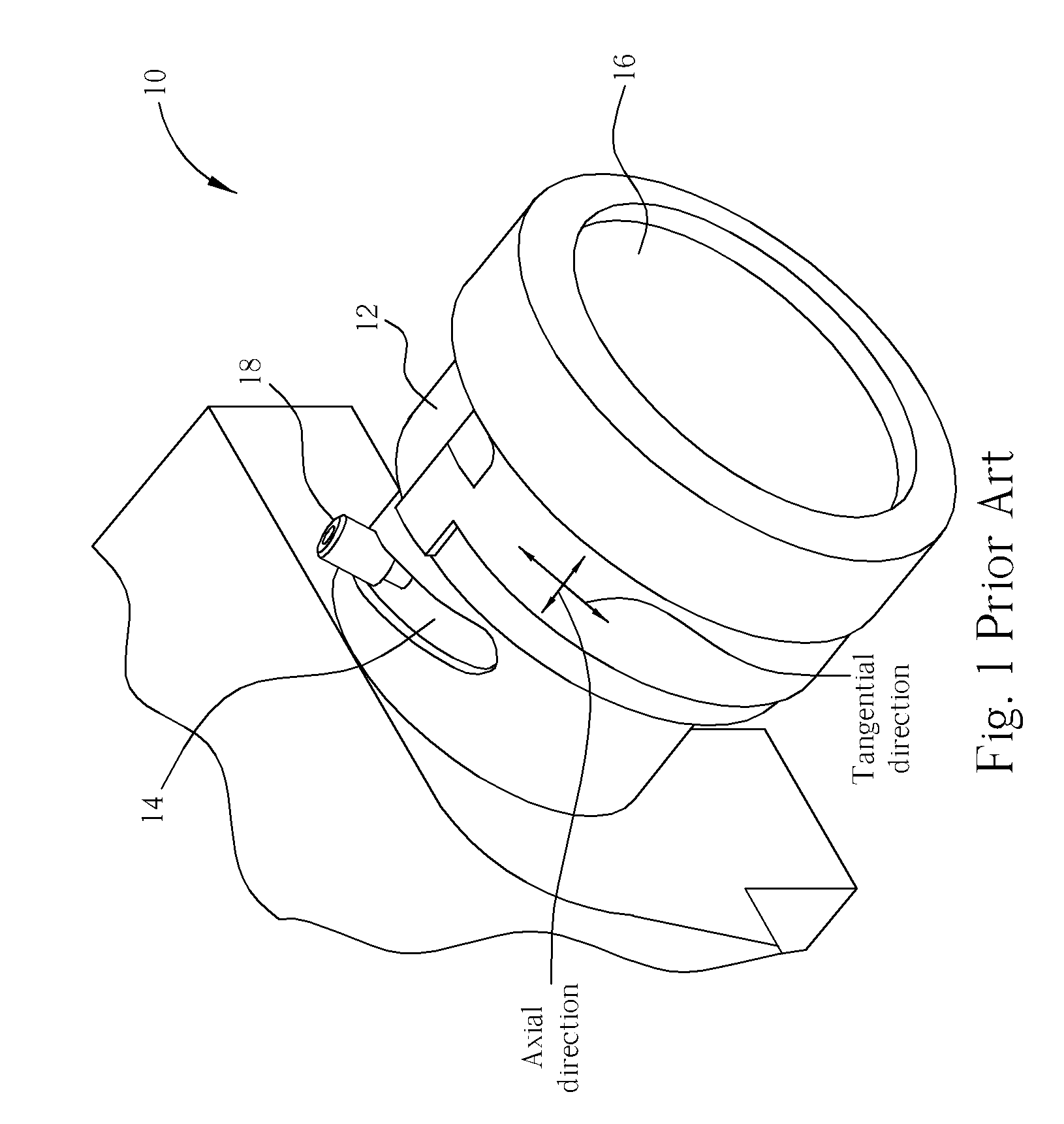
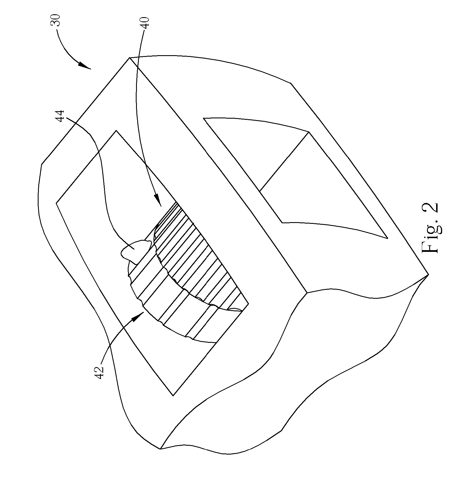
[0020] Please refer to FIG. 2 and FIG. 3. FIG. 2 is a perspective drawing of an optical assembly 30 according to an embodiment of the present invention. FIG. 3 is a schematic diagram of internal components of the optical assembly 30 according to the embodiment of the present invention. The optical assembly 30 can be an optical assembly of a projector. As shown in FIG. 3, the optical assembly 30 includes a barrel 32 including a spiral slot 34, a lens 36 installed inside the barrel 32 for magnifying an image, and a rod 38 for adjusting magnification of the lens 36. One end of the rod 38 is installed inside the slot 34 of the barrel 32 in a slidable manner. The movement of the rod 38 is constrained by the slot 34 of the barrel 32. That is, a displacement of the rod 38 consists of a tangential displacement and an axial displacement relative to the barrel 32. As shown in FIG. 2, the optical assembly 30 further includes a magnification-adjusting mechanism 40 installed outside and around t...


PUM


Abstract

An optical assembly includes a barrel including a slot, a lens installed inside the barrel for magnifying an image, a magnification-adjusting mechanism installed outside and around the barrel including an adjusting loop installed outside the barrel in a rotatable manner including a groove on a side facing the barrel, and a roller installed between the adjusting loop and the barrel. The optical machine further includes a rod for adjusting the magnification of the lens. One end of the rod is installed inside the slot of the barrel in a slidable manner, and another end of the rod is installed inside the groove of the adjusting loop in a slidable manner.

Description

BACKGROUND OF THE INVENTION [0001] 1. Field of the Invention [0002] The present invention relates to an optical assembly with a lens magnification-adjusting function, and more particularly, to an optical assembly having tangential actuation. [0003] 2. Description of the Prior Art [0004] In conferences, a host can project related material or graphs onto a screen with a projector to let participants better understand the discussion. However, with the advance of video / audio equipments and storage media, such as high power stereos and large capacity DVDs, families can also enjoy the same experience in a home theater through an extra-large screen and a projector in combination with a stereo sound system. [0005] Please refer to FIG. 1. FIG. 1 is a schematic diagram of an optical assembly 10 of a projector of the prior art. The optical assembly 10 includes a barrel 12 including a spiral slot 14, a lens 16 installed inside the barrel 12 for magnifying an image, and a rod 18. The rod 18 is i...

Claims


Application Information

Patent Timeline
IPC IPC(8): G02B15/14
CPCG02B7/10
Inventor WANG, YEN-LINHUANG, HSU-HSINLIU, HUNG-WEN
Owner BENQ CORP
Why Eureka
Try Eureka