
Small motor

a small motor and motor body technology, applied in the field of small motors, can solve the problems of difficulty in use of smaller toy vehicles or robots, increase the size of the motor body, etc., and achieve the effects of constant friction resistance, efficient release, and stable holding

Inactive Publication Date: 2007-01-04
MORI HIDEYUKI
View PDF7 Cites 22 Cited by
  • Summary
  • Abstract
  • Description
  • Claims
  • Application Information

AI Technical Summary

Benefits of technology

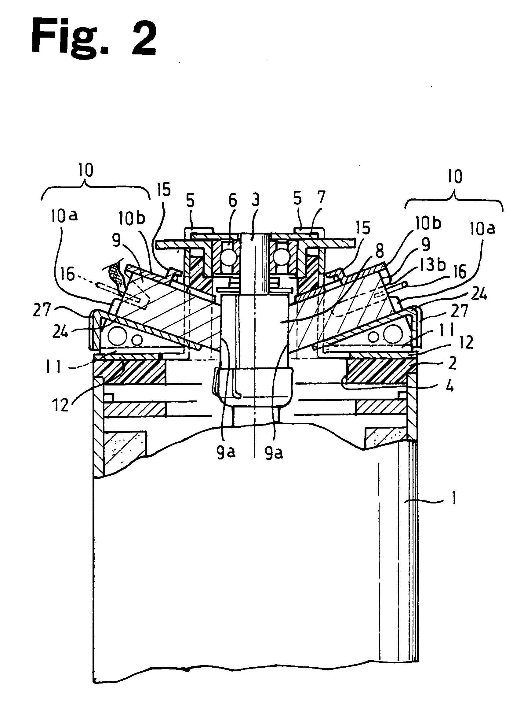
[0010] With this structure, since the axis of the motor brush intersects the center line of the rotor shaft at a specified angle other than a right angle, the motor brush can be in contact with the commutator at a wide contact area, thus increasing the current-carrying capacitor of the motor brush. This enables the DC motor to be driven at a high toque without increasing the size of the motor.
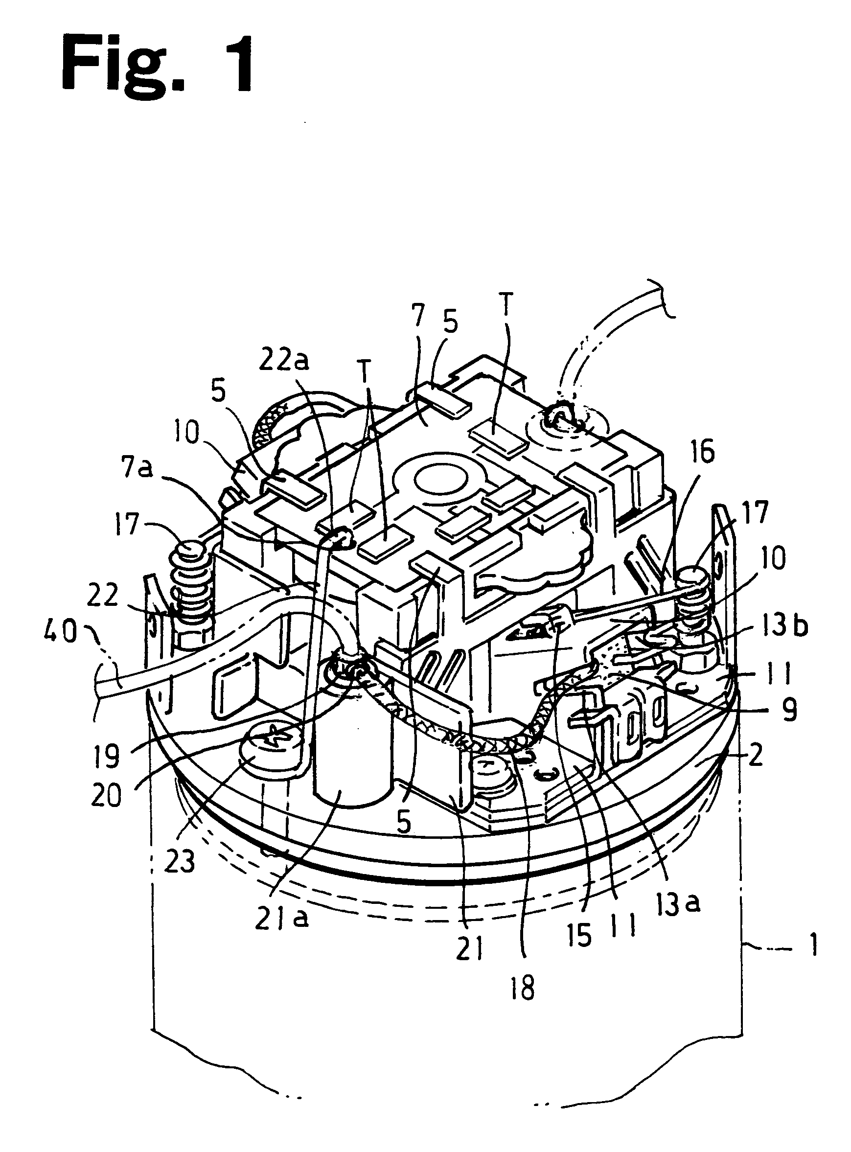
[0019] Preferably, the small motor further includes; a mounting member having a support cylinder on the end cover, the mounting member being screwed on the end cover together with the end of a conductive wire connected to the brush; and a power-supply round faston terminal connected to the end of the power-source wire and pushed into the support cylinder. This arrangement enables the length of the conductive wire to be decreased, thus preventing the electrical interference between the conductive wire and other components.

Problems solved by technology

Therefore, increasing the size of the motor brush to increase the current-carrying capacity at the contact between the motor brush and the commutator increases the size of the motor body, thus posing the problem of difficulty in use for smaller toy vehicles or robots.

Method used


Image

  • Small motor
  • Small motor
  • Small motor

Examples


Embodiment Construction

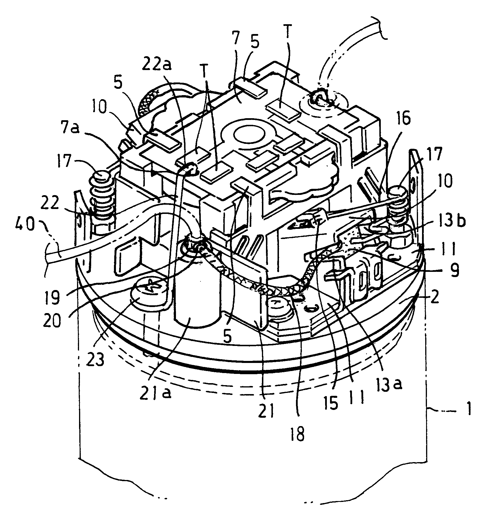
[0030] The small motor in FIG. 1 includes a closed-bottom cylindrical motor case 1 for accommodating a motor body. The motor case 1 has a ring-shaped plate end cover 2 at the open end. Although not shown because of having no relation to the principal part of the invention, the motor case 1 accommodates a stator having a field coil and a rotor having an armature coil, similarly to conventional motors.

[0031] Referring to FIG. 2, the end cover 2 has a central hole 4. One end of a rotor shaft 3 passes through the central hole 4 without contact with the end cover 2. The end cover 2 has a pair of bearing retainers 5 thereon. The bearing retainers 5 are opposed to each other with the rotor shaft 3 as the center. The bearing retainers 5 retain a bearing 6 therebetween. The bearing 6 rotatably supports the upper end of the rotor shaft 3.

[0032] The bearing retainers 5 also retain a circuit board 7 therebetween. The retaining is facilitated by crimping the upper end (projection) of the beari...


PUM


Abstract

A small motor includes: a rotor shaft having a commutator; and a motor brush in contact with the commutator of the rotor shaft. The axis of the motor brush intersects the center line of the rotor shaft at a specified angle other than a right angle. This arrangement enables the motor brush to be brought into contact with the commutator at a wide contact area. This increases the current-carrying capacitor of the motor brush, thus allowing the DC motor to be driven by a large toque without increasing the size of the motor.

Description

BACKGROUND [0001] 1. Field of the Invention [0002] The present invention relates to a small motor for use in radio control and so on. [0003] 2. Background of the Invention [0004] Toy vehicles and airplanes that run or fly by radio remote control include a DC small motor as power source. [0005] In a DC motor, an electric current supplied from a battery is transmitted via a motor brush to a semicircular commutator in contact with the motor brush and then introduced to an armature conductor. The direction of the current is switched every half turn of a rotor having the armature conductor to provide a running torque in the same direction. [0006] The driving torque of the DC motor depends on the amperage of the armature, which increases with an increase in armature current. Accordingly, to obtain a high driving torque, it is necessary to pass a large current to the armature conductor (armature coil) via the motor brush and the commutator, so that it is desirable to increase the current-c...

Claims


Application Information

Patent Timeline
Patent Type & Authority Applications(United States)
IPC IPC(8): H02K11/00
CPCH01R39/385H01R39/46H02K13/10H02K5/225H02K5/148
Inventor MORI, HIDEYUKI
Owner MORI HIDEYUKI
Learn More