Linear motor and linear compressor having same

a linear compressor and motor technology, applied in the direction of positive displacement liquid engine, piston pump, magnetic circuit shape/form/construction, etc., can solve the problems of deteriorating compressor performance, increasing the weight of the mover, increasing the manufacturing cost of the motor and compressor, etc., to reduce the centering force, increase the thrust, and increase the motor power

Active Publication Date: 2020-12-17
LG ELECTRONICS INC
View PDF4 Cites 0 Cited by
  • Summary
  • Abstract
  • Description
  • Claims
  • Application Information

AI Technical Summary

Benefits of technology

[0071]The linear motor according to the present disclosure and the linear compressor having the same fixedly couple a plurality of magnets to the stator and magnetize the plurality of magnets in the same direction, so that the thrust increases so that motor power can increase by increasing thrust instead of reducing the centering force for the reciprocating mover core. Accordingly, it is possible to reduce the amount of the magnet used compared to the same motor output, and when using a ferrite magnet, the motor power of the desired degree can be obtained without increasing the size of the motor. In addition, when the Nd magnet is used, material cost can be reduced by reducing motor usage.
[0072]In addition, according to the present disclosure, as the outer stator is provided with pole portions on both sides around the winding coil, respectively, and the inner stator is provided with magnets on both sides with the central core interposed therebetween, the alpha waveform of the motor is formed to be symmetrical based on the center of the magnetic path. Accordingly, the effective stroke section for the mover core becomes longer, so that the mover core can be more accurately controlled, thereby improving motor performance.
[0073]In addition, according to the present disclosure, as the magnet is inserted into and coupled to the outer circumferential surface of the inner stator, it is possible to easily perform an assembly operation and a magnetization operation of the magnet. Furthermore, as a plurality of magnets spaced apart in the axial direction by the central core are magnetized in the same direction, a magnetization operation for the magnet can be further easily performed.
[0074]In addition, according to the present disclosure, in a linear motor having a mover inside the stator, as the magnet is inserted into and coupled to the inner circumferential surface of the stator, it is possible to easily perform the assembly operation and the magnetization operation for the magnet. Furthermore, as the plurality of magnets are magnetized in the same direction with the fixed-side core protrusion interposed therebetween, it is possible to more easily magnetize the magnet, and reduce the length of the mover to increase the efficiency of the motor.
[0075]In addition, according to the present disclosure, a plurality of magnets are fixedly coupled to the stator, but by magnetizing the plurality of magnets in the same direction, instead of reducing the centering force for the reciprocating mover core, the thrust increases to increase the motor output. Accordingly, it is possible to reduce the amount of the magnet used compared to the same motor output, and when using a ferrite magnet, the motor power of the desired degree can be obtained without increasing the size of the motor. In addition, when the Nd magnet is used, material cost can be reduced by reducing motor usage.

Problems solved by technology

Since the Nd magnet has high magnetic power but has high prices, the manufacturing cost of motors and compressors increase.
Since the ferrite magnet has low price but requires a relatively large amount of magnet due to the low magnetic force of the ferrite magnet, the weight of the mover increases.
Accordingly, there is a problem that the thrust for pushing the mover in a direction of the top dead center or the bottom dead center is weakened to deteriorate the performance of the compressor to which this motor is coupled.
In addition, in the linear motor in the prior art, there are problems that, as one air gap is eccentrically formed from the center of the magnetic path, the alpha waveform is formed to be asymmetrical, and, as the inductance increases, the control characteristics of the motor is deteriorated, and the motor efficiency is deteriorated.
In addition, in the linear motor in the prior art, there is a problem that since a magnet is mounted on the inner circumferential surface of the core, a magnetization operation for the magnet becomes difficult from each other.
In particular, there is a problem that as a plurality of magnets are magnetized in different directions from each other, the magnetization operation for the magnet described above becomes more difficult.
The core loss is an inevitable loss to obtain a predetermined magnetic flux density at a specific frequency, and there is a problem that the efficiency of the linear motor is further deteriorated.

Method used


Image

  • Linear motor and linear compressor having same
  • Linear motor and linear compressor having same
  • Linear motor and linear compressor having same

Examples


Embodiment Construction

ressor according to the present embodiment will be described in more detail with reference to the drawings. However, even in different embodiments, the same or similar reference numerals are assigned to the same or similar components as the previous embodiment, and overlapping descriptions thereof may be omitted. In addition, in describing the embodiments disclosed in this specification, when it is determined that detailed descriptions of related known technologies may obscure the gist of the embodiments disclosed herein, detailed descriptions thereof may be omitted.

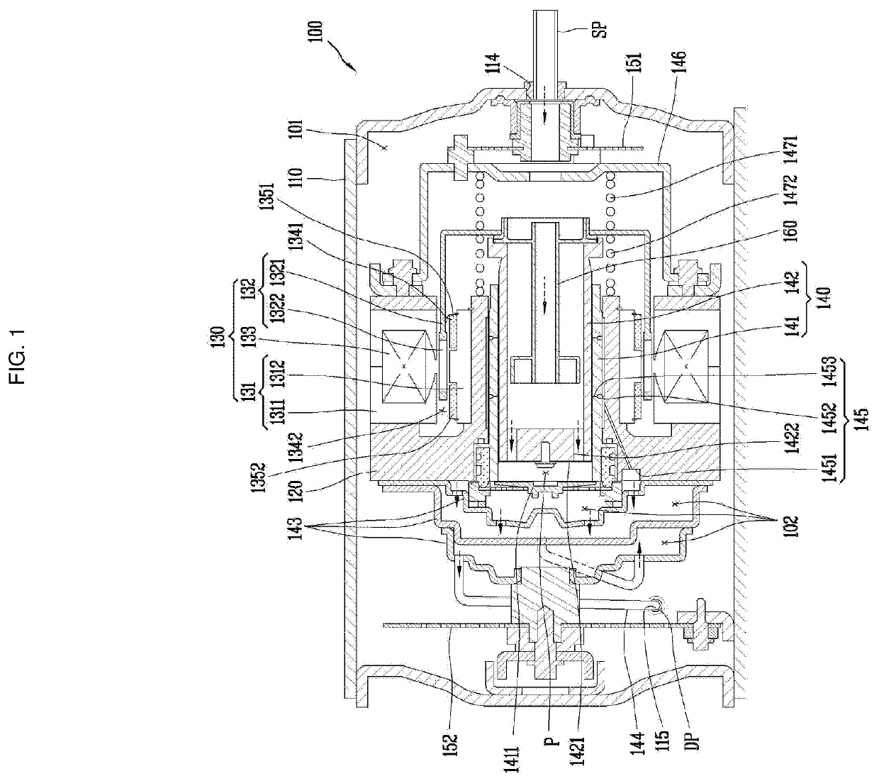
[0175]FIG. 11 is a longitudinal sectional view illustrating another embodiment of the linear compressor according to the present disclosure. Referring to FIG. 11, the linear compressor 100 of the present embodiment includes a casing 110, a frame 120, a driving unit 130, and a compression unit 140.

[0176]The casing 110 may form a sealed space. The sealed space may be the suction space 101 filled with the refrigerant which ...


PUM


Abstract

In a linear motor and the linear compressor having the same according to the present disclosure, a plurality of magnets are coupled to a stator equipped with a winding coil, and a mover core made of magnetic material instead of a permanent magnet is provided on the mover, and by the magnetizing plurality of magnets in the same direction, the motor output can increase by increasing thrust instead of decreasing the centering force for the mover core. In addition, as it is applied to a two-pore motor, it is possible to easily control the mover core and to easily perform an assembly operation and a magnetization operation for the magnet. In addition, as the stator is made of a grain-oriented core, core loss may be reduced and the motor efficiency may be improved.

Description

TECHNICAL FIELD[0001]The present disclosure relates to a linear motor in which a mover reciprocates linearly and a linear compressor having the same.BACKGROUND ART[0002]A linear motor is a motor in which a mover reciprocates linearly by interaction with a stator, and a linear compressor is a compressor in which a piston is coupled to a mover by employing this linear motor. Therefore, the linear compressor performs a suction stroke that the piston coupled to the mover moves to the bottom dead center (BDC) and a compression stroke that the piston coupled to the mover moves to the top dead center (TDC), while the piston reciprocates in a cylinder.[0003]The linear motor includes a core through which magnetic flux flows, a winding coil to which a current is applied, and a magnet forming a magnetic circuit with the core and the winding coil. The core includes an inner core and an outer core, which are formed in a cylindrical shape, respectively, and are provided inside and outside, respec...

Claims


Application Information

Patent Timeline
Patent Type & Authority Applications(United States)
IPC IPC(8): H02K41/03H02K1/14H02K1/16H02K1/34F04B35/04F04B39/12F04B39/00F04B49/06
CPCF04B39/121F04B39/122F04B35/045H02K1/34F04B39/0016H02K1/16H02K1/146H02K41/03F04B49/06H02K1/145H02K33/16H02K7/14H02K2213/03F04B39/126
Inventor CHOI, KICHULHONG, EONPYOKIM, JAEBEUM
Owner LG ELECTRONICS INC
Why Eureka
Try Eureka