Power-on reset circuit

a technology of power-on reset and circuit, which is applied in the direction of pulse automatic control, electronic switching, pulse technique, etc., can solve the problem that the conventional power-on reset circuit cannot meet this requirement, and achieve the effect of accurately setting and adjusting the reset finishing voltag

Inactive Publication Date: 2007-01-04
AIMTRON TECH CORP
View PDF9 Cites 59 Cited by
  • Summary
  • Abstract
  • Description
  • Claims
  • Application Information

AI Technical Summary

Benefits of technology

[0006] An object of the present invention is to provide a power-on reset ci

Problems solved by technology

Unfortunately, conventional power-on reset

Method used


Image

  • Power-on reset circuit
  • Power-on reset circuit
  • Power-on reset circuit

Examples


Embodiment Construction

[0015] The preferred embodiments according to the present invention will be described in detail with reference to the drawings.

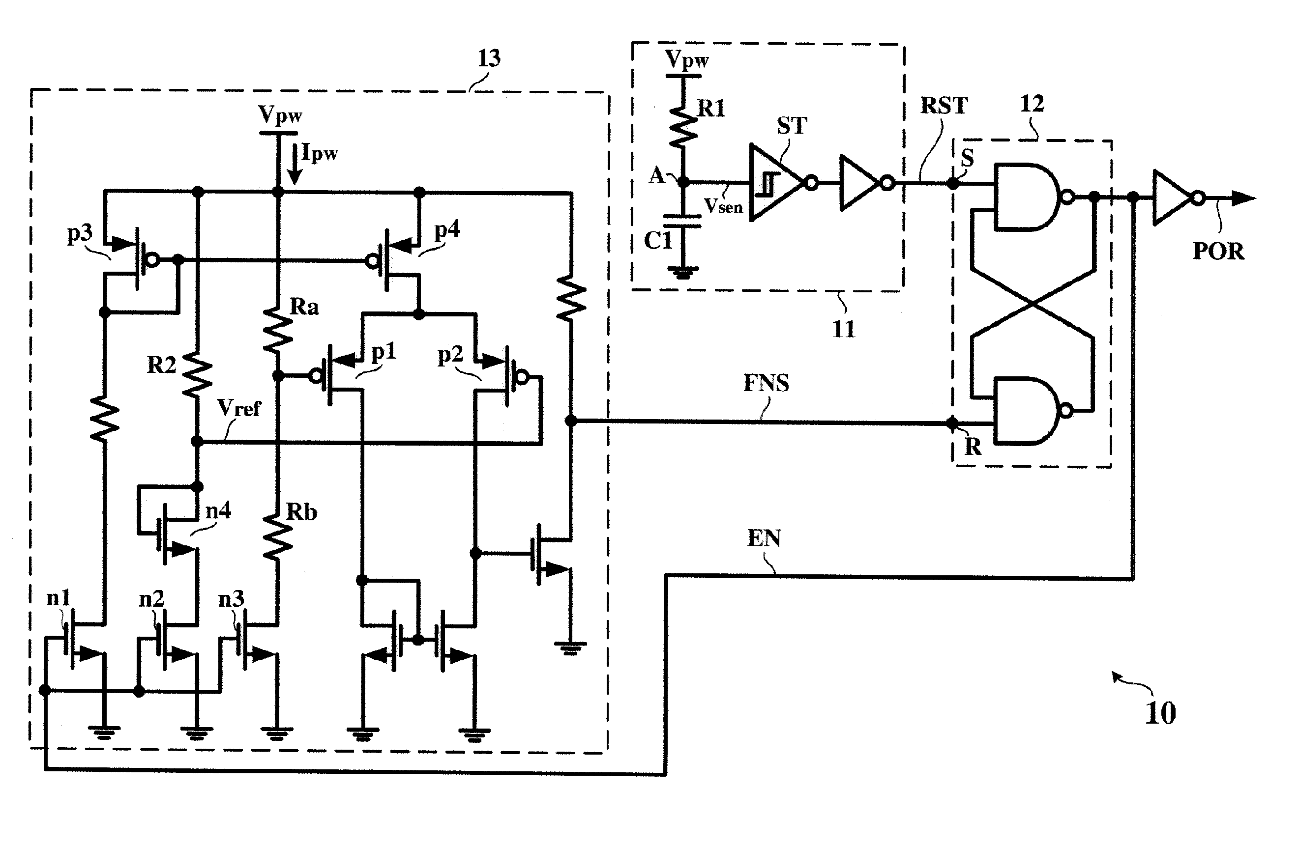
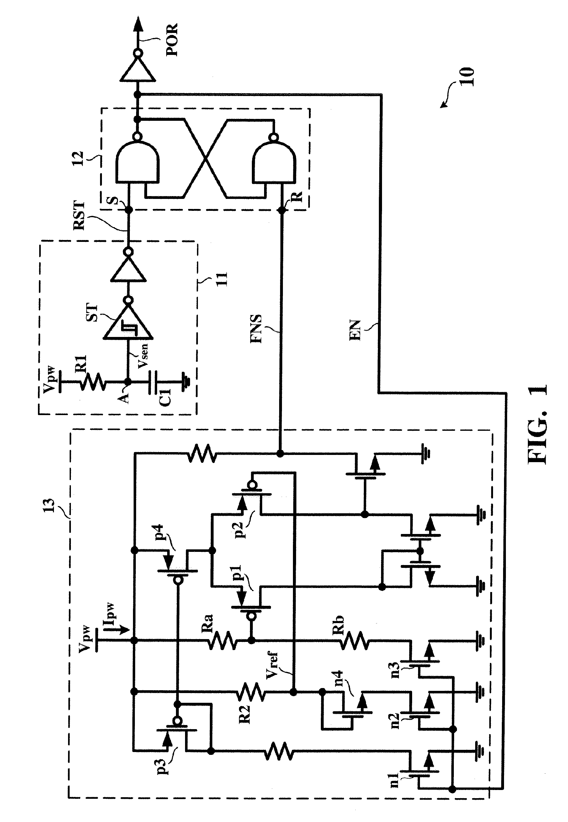
[0016]FIG. 1 is a detailed circuit diagram showing a power-on reset circuit 10 according to a first embodiment of the present invention. Referring to FIG. 1, the power-on reset circuit 10 includes a reset starting circuit 11, a latch circuit 12, and a reset finishing circuit 13. The reset starting circuit 11 generates and applies a reset starting signal RST to the latch circuit 12. The reset finishing circuit 12 generates and applies a reset finishing signal FNS to the latch circuit 12. The reset finishing circuit 13 is activated by an enable signal EN in feedback from an output terminal of the latch circuit 12. In response to the reset starting signal RST and the reset finishing signal FNS, the latch circuit 12 determines states of a power-on reset signal POR. The power-on reset signal POR is applied to other circuits (not shown) of the integrated circuit ...


PUM


Abstract

A power-on reset circuit has a reset starting circuit, a reset finishing circuit, and a latch circuit. The reset starting circuit generates a reset starting signal in response to a power voltage. When the power voltage reaches a predetermined reset finishing voltage, the reset finishing circuit generates a reset finishing signal. The latch circuit generates a power-on reset signal having a first state and a second state. In response to the reset starting signal, the latch circuit causes the power-on reset signal to transition to the first state. In response to the reset finishing signal, the latch circuit causes the power-on reset signal to transition to the second state.

Description

BACKGROUND OF THE INVENTION [0001] 1. Field of the Invention [0002] The present invention relates to a power-on reset circuit and, more particularly, to a power-on reset circuit capable of accurately setting a reset finishing voltage. [0003] 2. Description of the Prior Art [0004] Most integrated circuit chips usually include a plenty of transistors and basic logic units. After the power is turned on, the power voltage is rising from zero to a predetermined stable value at which the integrated circuit chip is operated normally. In order to avoid any uncertainty with initial states of the transistors and logic units in the integrated circuit chip, it is necessary before the power voltage reaches the stable value to have performed a reset operation phase with respect to the transistors and logic units. For this reason, a power-on reset circuit is designed for providing a power-on reset signal to control the starting as well as finishing of the reset operation phase before the power vol...

Claims


Application Information

Patent Timeline
IPC IPC(8): H03L7/00
CPCH03K17/223
Inventor CHEN, CHI-YANGLEE, RONG-CHIN
Owner AIMTRON TECH CORP
Why Eureka
Try Eureka