Low current power-on reset circuit and method

a low-current, power-on reset technology, applied in the direction of pulse automatic control, pulse technique, electronic switching, etc., can solve the problems of long delay, very slow response of por circuit b>1/b> to a ramp-down of vsub>dd /sub>, and very little power dissipation

Active Publication Date: 2011-03-31
TEXAS INSTR INC
View PDF8 Cites 36 Cited by
  • Summary
  • Abstract
  • Description
  • Claims
  • Application Information

AI Technical Summary

Benefits of technology

[0012]It is an object of the invention to provide a power-on reset circuit that rapidly discharges a storage capacitor that determines a delay between an interruption or loss of power supply voltage and an edge of a power-on reset signal generated by the power-on reset circuit.
[0013]It is another object of the invention to provide a power-on reset circuit that rapidly discharges a storage capacitor that determines a delay between an interruption or loss of power supply voltage and an edge of a power-on reset signal generated by the power-on reset circuit and dissipates very little power.

Problems solved by technology

This results in the previously mentioned long delay before power-on reset signal VPOR transitions from a logic high “1” level to a logic low “0” level in response to the interruption of VDD.
However, the response of POR circuit 1 to a ramp-down of VDD is very slow, due to the previously described extremely slow discharge of capacitor C0.
There also is an unmet need for a power-on reset circuit that rapidly discharges a storage capacitor that determines a delay between an interruption or loss of power supply voltage and an edge of a power-on reset signal generated by the power-on reset circuit, occupies a very small amount of integrated circuit chip area, and dissipates very little power.

Method used


Image

  • Low current power-on reset circuit and method
  • Low current power-on reset circuit and method
  • Low current power-on reset circuit and method

Examples


Embodiment Construction

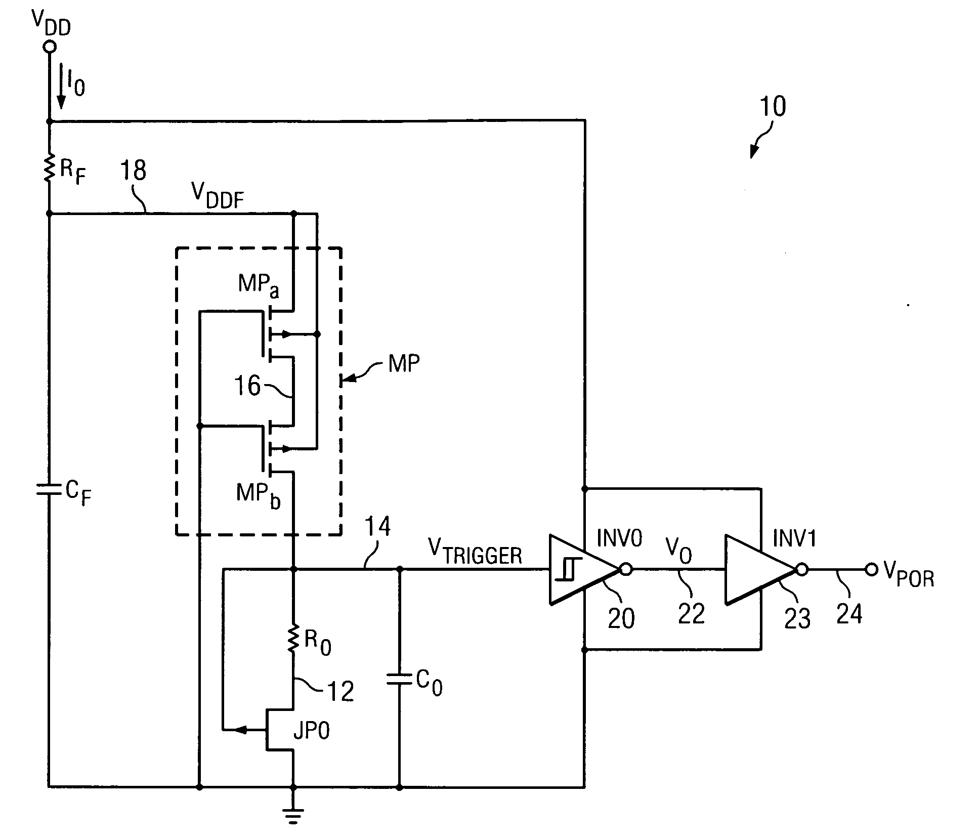
[0029]Referring to FIG. 2, POR circuit 10 includes a filter resistor RF connected between VDD and conductor 18. A filter capacitor CF is connected between conductor 18 and ground (or VSS). The filter composed of resistor RF and capacitor CF produces a filtered supply voltage VDDF on conductor 18 to prevent false triggering of POR circuit 10. P-channel transistor or transistor circuit MP is connected between conductors 14 and 18. The gate of transistor MP is connected to ground. Transistor or transistor circuit MP can be implemented as a single transistor with its gate connected to ground or by means of two series-connected P-channel transistors MPa and MPb with their gates connected to ground in order to make the layout of POR circuit 10 more compact, as shown. Conductor 14 in FIG. 2 is connected to one terminal of a discharge resistor R0, one terminal of a discharge capacitor C0, the gate of a P-channel JFET (Junction Field-Effect Transistor) JP0, and the input of an inverting Schm...


PUM


Abstract

A power-on reset (POR) circuit includes a first transistor (MPa) having a source coupled to a first supply voltage (VDD) and a gate coupled to a second supply voltage (GND). A resistor (R0) has a first terminal coupled by a depletion mode transistor (JP0) to the second supply voltage and a second terminal coupled to a drain of the first transistor. A Schmitt trigger (20) has an input coupled to receive a first signal (VTRIGGER) on a conductor (14) coupled to the second terminal of the resistor and a terminal of a capacitor (C0), for producing an output voltage (VO) representative of a power-on reset signal (VPOR) in response to an interruption of the first supply voltage (VDD).

Description

BACKGROUND OF THE INVENTION[0001]The present invention relates generally to “power-on reset” (POR) circuits, particularly to a power-on reset circuit which dissipates very little power, occupies a very small amount of integrated circuit chip area, and rapidly discharges a storage capacitor that establishes a delay between an interruption in power supply voltage and an edge of a power-on reset signal generated by the power-on reset circuit.[0002]A POR circuit resets circuitry, especially digital logic circuitry, when the power supply voltage falls below a minimum acceptable operating voltage. Preferably, a POR circuit should occupy as little integrated circuit chip area as possible. It should also consume as little power and draw as little current (e.g., less than 500 nanoamperes) from the power supply. Preferably, a POR circuit should not generate a POR output signal in response to minor fluctuations of the power supply voltage.[0003]Power-on reset (POR) circuit 1 in Prior Art FIG. ...

Claims


Application Information

Patent Timeline
Patent Type & Authority Applications(United States)
IPC IPC(8): H03L7/00
CPCH03K17/223
Inventor SANBORN, KEITH E.MOLINA, JOHNNIE F.
Owner TEXAS INSTR INC
Why Eureka
Try Eureka