Electronic candle

a technology of electronic candles and candles, applied in the field of candles, can solve the problem that the electronic device does not work automatically, and achieve the effect of preventing interruption of operation and preventing quick vaporization of good smell

Inactive Publication Date: 2007-01-04
YU SHUNG LUN
View PDF3 Cites 24 Cited by
  • Summary
  • Abstract
  • Description
  • Claims
  • Application Information

AI Technical Summary

Benefits of technology

[0006] The present invention has been accomplished under the circumstances in view. According to one aspect of the present invention, the electronic candle comprises a candle body, the candle body comprising a center stick of wax and a perfume stick surrounding the center stick of wax, the center stick of wax having a wick, the perfume stick being formed of a mixture containing a wax and a perfume; an electronic device fastened to a bottom side of the perfume stick, the electronic device comprising a circuit board adapted to produce sound and lighting effects, and a photo sensor adapted to control the operation of the circuit board; and at least one optical fiber embedded in the center stick and adapted to transmit light from the flame burning at the wick of the center stick to the photo sensor to induce the photo sensor. According to another aspect of the present invention, the candle body further comprises an isolating layer surrounding the perfume stick to prevent quick vaporization of the good smell of the perfume contained in the perfume stick. According to still another aspect of the present invention, the perfume stick can be made of a jelly candle with a perfume contained therein. According to still another aspect of the present invention, a protective end cap is fastened to the wick to prevent contact of the wick with the electronic device. The protective end cap is a heat conducting ring made metal, ceramics, or glass. According to still another aspect of the present invention, the electronic device further comprises a tubular shade provided at the top side thereof. The shade has a plurality of peripheral holes for guiding in light from the light emitting elements of the circuit board to induce the photo sensor, preventing interruption of the operation of the photo sensor due to floating of the flame upon a wind.

Problems solved by technology

According to this design, the user controls the operation of electronic device manually through a manual switch, i.e., the electronic device does not work automatically upon burning of the wick of the candle body.

Method used


Image

  • Electronic candle
  • Electronic candle
  • Electronic candle

Examples


Embodiment Construction

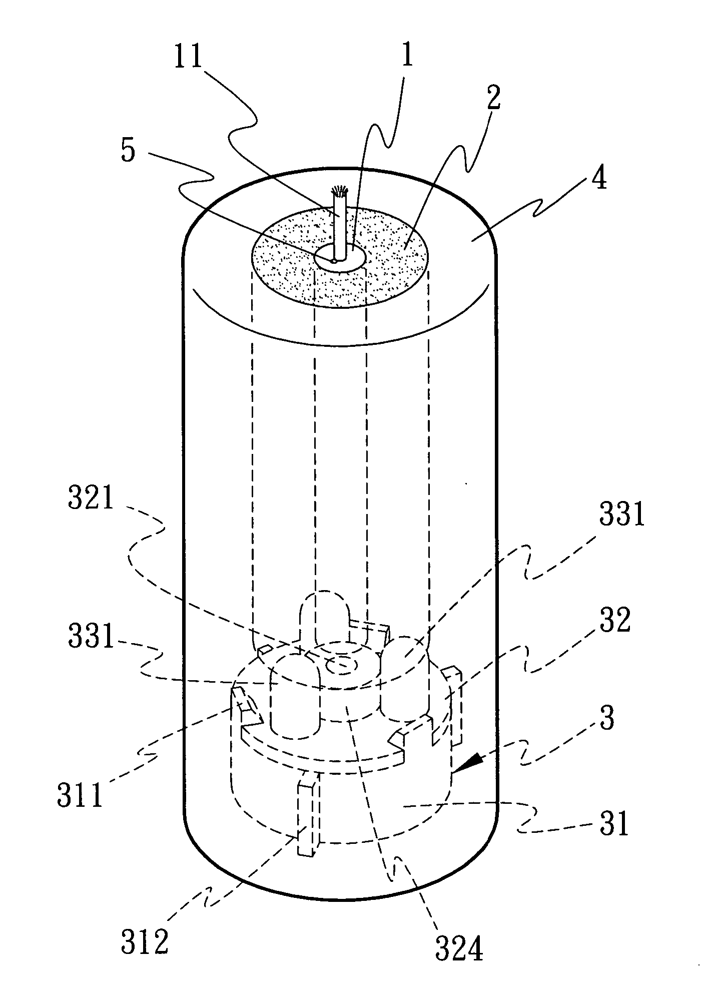
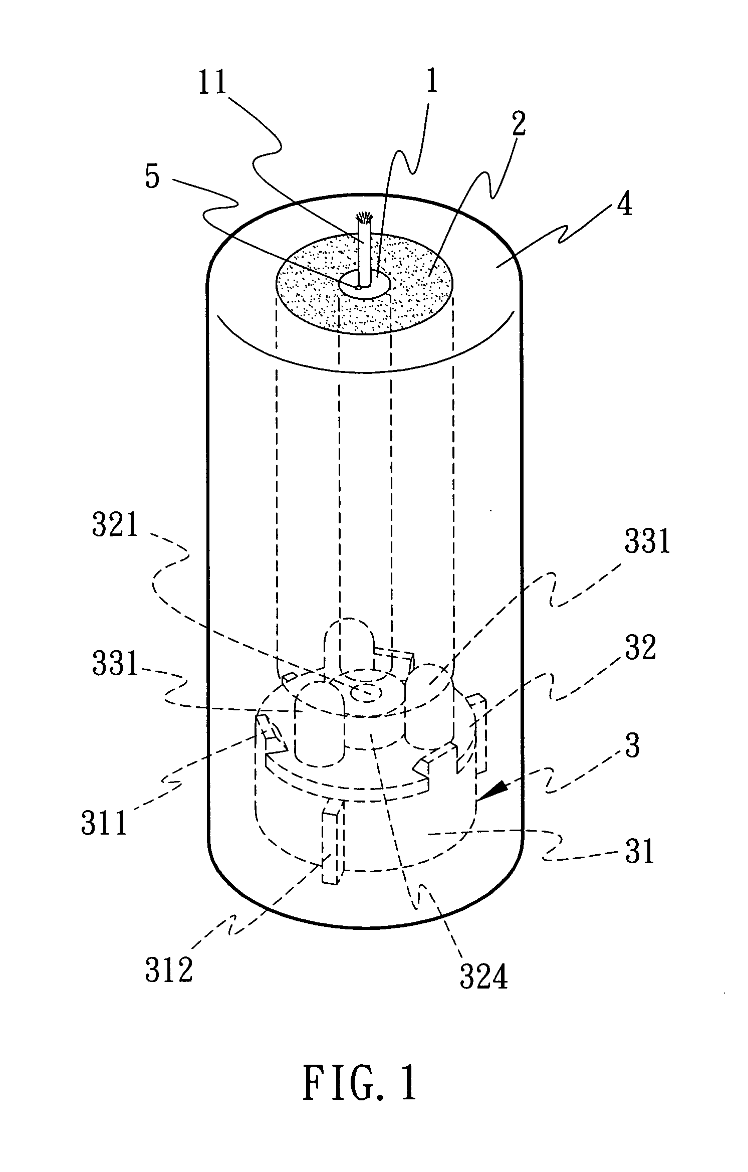
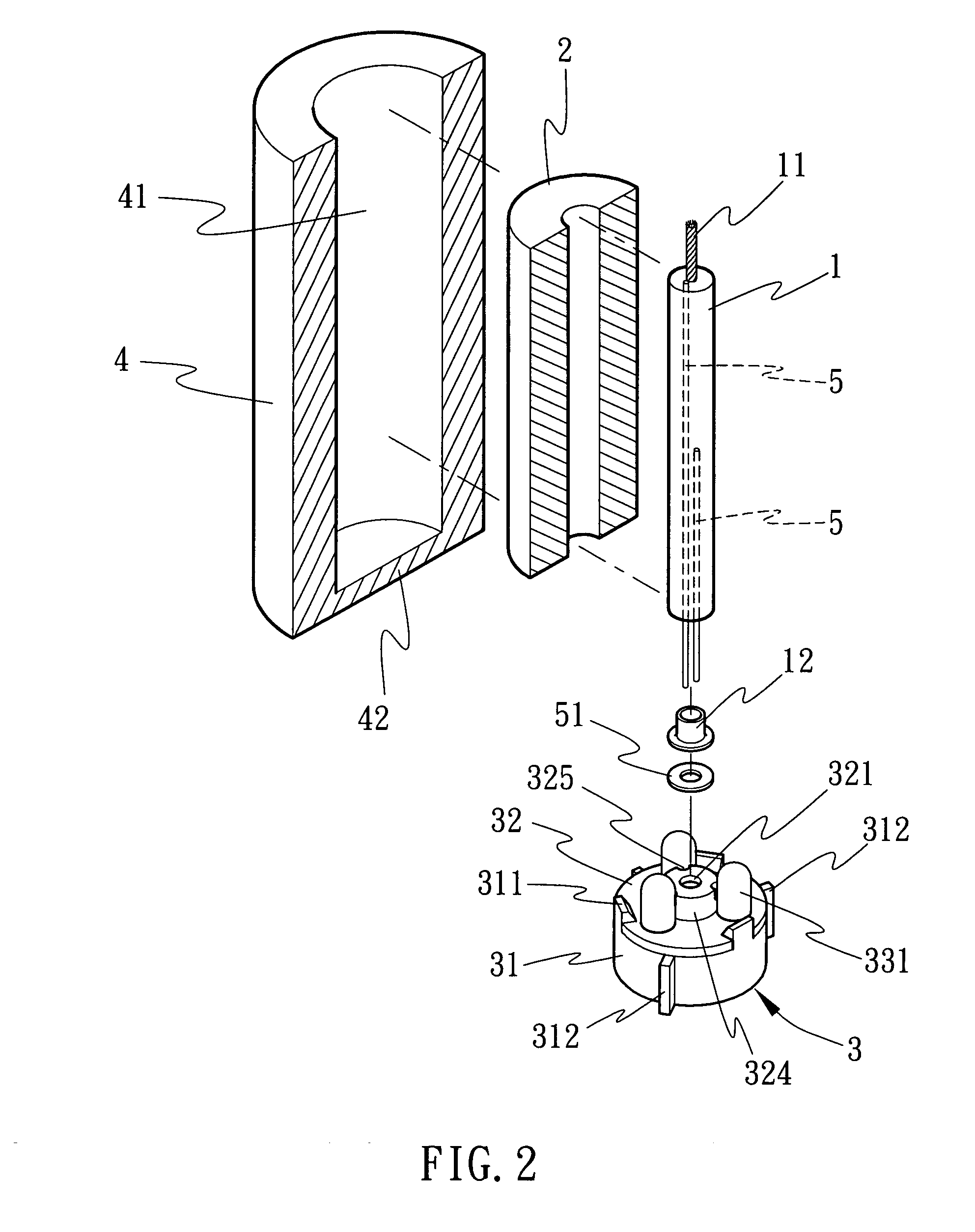
[0016] Referring to FIGS. 1˜3, an electronic candle in accordance with the present invention is shown comprising a center stick 1, a perfume stick 2, an electronic device 3, and an outer isolating tube 4. The center stick 1 is a stick of wax concentrically axially set through the perfume stick 2 and forming with the perfume stick 2 the body of the electronic candle. The outer isolating tube 4 is a tube of isolating substance, for example, wax that surrounds the perfume stick 2, preventing quick loss of the good smell of the perfume stick 2.

[0017] The center stick 1 is a stick of wax having a wick 11 through it. The perfume stick 2 is a stick of wax added with a perfume such as lavender, Pythoncidere, bergamot, santalaceae, or the like. Alternatively, the perfume stick 2 can be a jelly candle with a perfume in it. The electronic device 3 is set in the bottom side of the electronic candle and controlled by light to produce a lighting or sound effect, having at least one, for example,...


PUM


Abstract

Disclosed is an electronic candle, which includes a center stick of wax with a wick for burning, a perfume stick surrounding the center stick of wax for giving off a good smell when melting, an electronic device, which is fastened to the perfume stick at the bottom side and has a circuit board and a photo sensor for driving the circuit board to produce sound and lighting effects during burning of the wick of the center stick of wax, and optical fibers embedded in the center stick for transmitting light from the flame burning at the wick to the photo sensor to induce the photo sensor.

Description

BACKGROUND OF THE INVENTION [0001] (a) Field of the Invention [0002] The present invention relates to candles and more particularly, to an electronic candle, which produces sound and lighting effects when the wick of the candle body thereof is burning. [0003] (b) Description of the Prior Art [0004] A conventional electronic candle is generally comprised of a candle body and an electronic device. The electronic device is used as holder means to hold the candle body, having a light emitting and / or sound generating circuit means. When the wick of the candle body is burning, the user can switch on the electronic device to emit light and / of to produce sound. [0005] According to this design, the user controls the operation of electronic device manually through a manual switch, i.e., the electronic device does not work automatically upon burning of the wick of the candle body. SUMMARY OF THE INVENTION [0006] The present invention has been accomplished under the circumstances in view. Accor...

Claims


Application Information

Patent Timeline
Patent Type & Authority Applications(United States)
IPC IPC(8): F23D3/16
CPCF21S6/001F23D3/16F21V23/0442
Inventor YU, SHUNG-LUN
Owner YU SHUNG LUN
Why Eureka
Try Eureka