
Method and apparatus for overcurrent protection in DC-DC power converters

a technology of dc-dc power converters and protection methods, which is applied in the direction of dc-dc conversion, power conversion systems, instruments, etc., can solve the problems of power converters, load circuit elements, or even interconnection wiring between them, and overcurrent conditions, so as to achieve compact digital logic and easy implementation as an integrated circuit

Active Publication Date: 2007-01-11
TEXAS INSTR INC
View PDF5 Cites 33 Cited by
  • Summary
  • Abstract
  • Description
  • Claims
  • Application Information

AI Technical Summary

Benefits of technology

[0021] Embodiments of the present invention achieve technical advantages as an overcurrent protection scheme that is operable over a wide range of power converter operating conditions. Advant

Problems solved by technology

A current that exceeds a design value, referred to as an overcurrent condition, can damage the power converter, load circuit elements, or even the interconnecting wiring therebetween.
An overcurrent condition can be caused, for example, by an unexpected operation of the load circuit, a blown or damaged circuit component, or an improper external connection to the circuit such as a misapplication of a test instrument.
Conflicting requirements in system designs that include power converters typically limit an output current to a limiting value to protect circuit components, but also require that the output voltage be brought to a regulated voltage level in as short a time interval as possible.
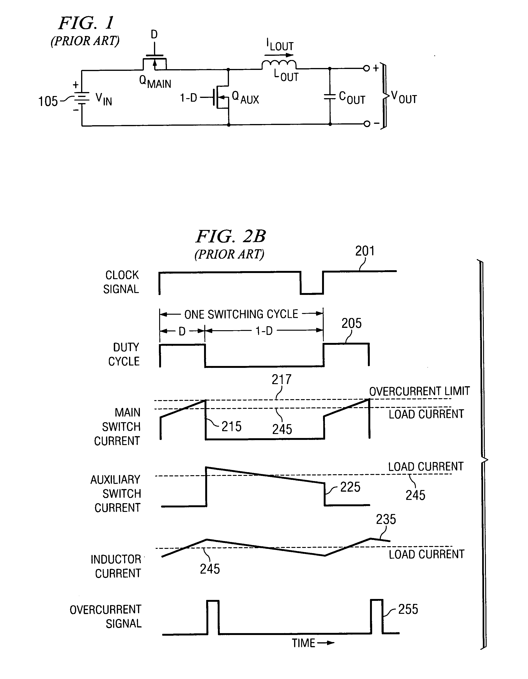
However, particularly for cases of low output voltage during startup or for a low-impedance fault coupled across the output of the power converter, the very short power converter duty cycle required to control the overcurrent condition may result in a runaway condition for power switch current.
In this manner, the current in the output inductor, which supplies the output current, increases from cycle to cycle, resulting in a runaway current condition for the power converter.
The control arrangement they describe, while increasing power conversion efficiency at light loads by intermittently disabling power switc

Method used


Image

  • Method and apparatus for overcurrent protection in DC-DC power converters
  • Method and apparatus for overcurrent protection in DC-DC power converters
  • Method and apparatus for overcurrent protection in DC-DC power converters

Examples


Embodiment Construction

[0029] The making and using of the presently preferred embodiments are discussed in detail below. It should be appreciated, however, that the invention provides many applicable inventive concepts that can be embodied in a wide variety of specific contexts. The specific embodiments discussed are merely illustrative of specific ways to make and use the invention, and do not limit the scope of the invention.

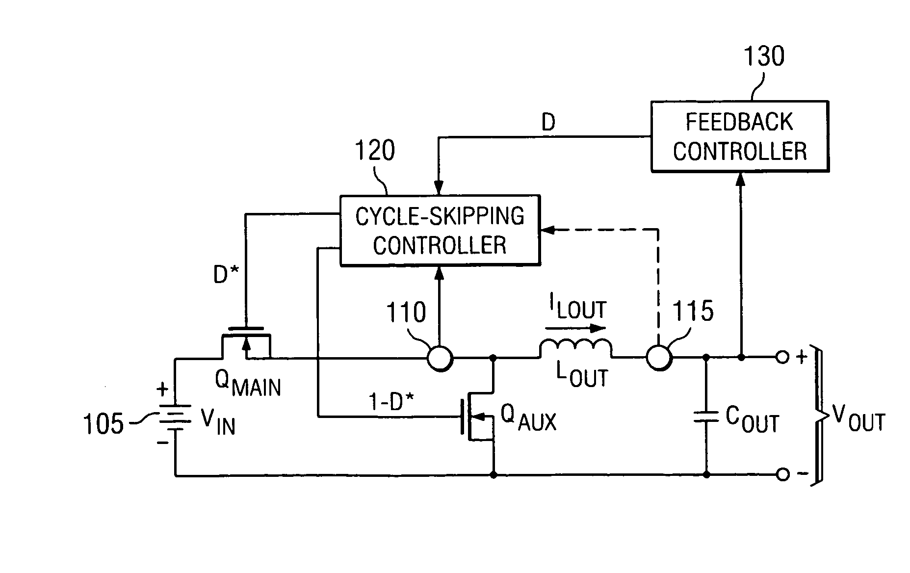
[0030] Embodiments of the invention will be described with respect to preferred embodiments in a specific context, namely a dc-dc power converter with dynamic frequency shift for overcurrent protection.

[0031] Alternative embodiments include isolated and non-isolated power converters, and power converters that step up or step down the input voltage to a higher or lower output voltage.

[0032] Preferred embodiments of the invention provide overcurrent protection employing at least two steps. In a first step of a preferred embodiment to providing overcurrent protection, an overcurrent...


PUM


Abstract

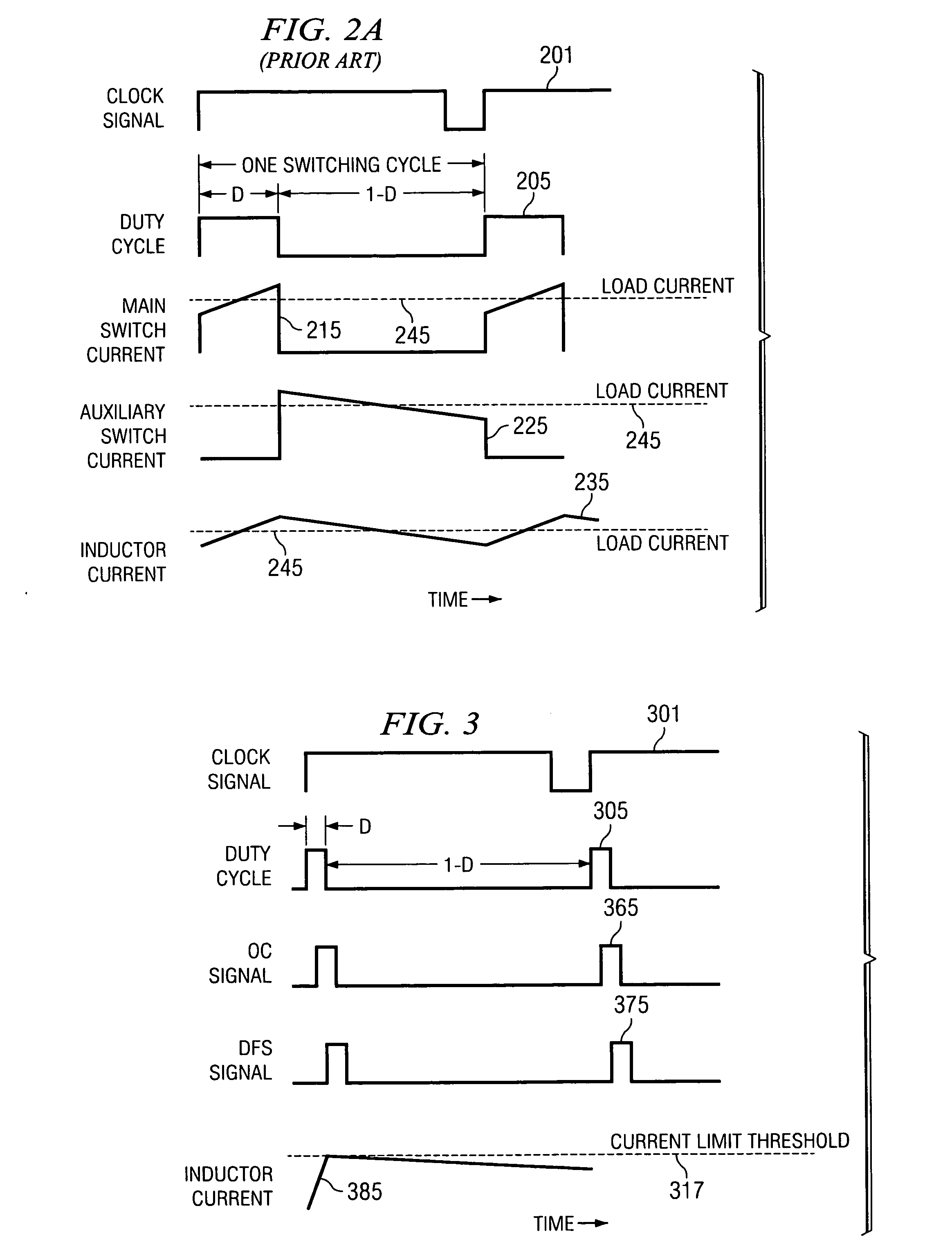
A controller and method for a switched-mode power converter adaptively provides overcurrent protection by detecting a current in the power converter exceeding a current limit during substantially a minimum on time of a power switch. A count N is computed for the number of consecutive active switching cycles that a current exceeds a current limit during substantially the minimum on time of the power switch. Conduction of the power switch is inhibited for a number of cycles that is a function of the count N, which is an increasing function of N. The function of the count N is preferably the function 2N−1. The count N is reset to zero if the current in the power converter does not exceed the current limit substantially during the minimum on time of the power switch. The controller can be easily implemented with a digital integrated circuit for a wide range of applications.

Description

TECHNICAL FIELD [0001] This invention relates generally to power converter circuits, and in particular, to a method and implementation of a control circuit for a switched-mode power converter that provides overcurrent protection. BACKGROUND [0002] A switched-mode power converter (also referred to as a “power converter”) is an electronic power processing circuit that converts an input voltage waveform into an output voltage waveform, both typically but not necessarily dc waveforms, by periodically switching power switches coupled to an inductive circuit element. The power switches are controlled with a conduction period referred to as a “duty cycle.” The duty cycle is a ratio represented by the conduction period of a power switch to a switching period thereof. Thus, if a power switch conducts for half of the switching period, the duty cycle for the power switch would be 0.5 (or 50 percent). Feedback controllers associated with power converters manage an operation thereof by controlli...

Claims


Application Information

Patent Timeline
IPC IPC(8): H02M3/335
CPCH02M3/156H02M1/32
Inventor TANG, NING
Owner TEXAS INSTR INC
Learn More