
Printer

Active Publication Date: 2007-01-11
CITIZEN WATCH CO LTD
View PDF6 Cites 20 Cited by
  • Summary
  • Abstract
  • Description
  • Claims
  • Application Information

AI Technical Summary

Benefits of technology

[0020] According to the present invention arranged in this manner, there may be provided a printer in which the printing paper can be loaded and replaced with ease and the control circuit unit can be protected against external adverse effects, such as external damage, exposure to dust, etc.

Problems solved by technology

Since the print control unit 145 is attached to the front of the unit mounting section 144b, it is susceptible to external adverse effects, such as external damage, exposure to dust, etc.
If the rolled paper 150 fails to be properly mounted on the holding members 151, therefore, it naturally falls and cannot be easily mounted again.

Method used


Image

  • Printer
  • Printer
  • Printer

Examples


Embodiment Construction

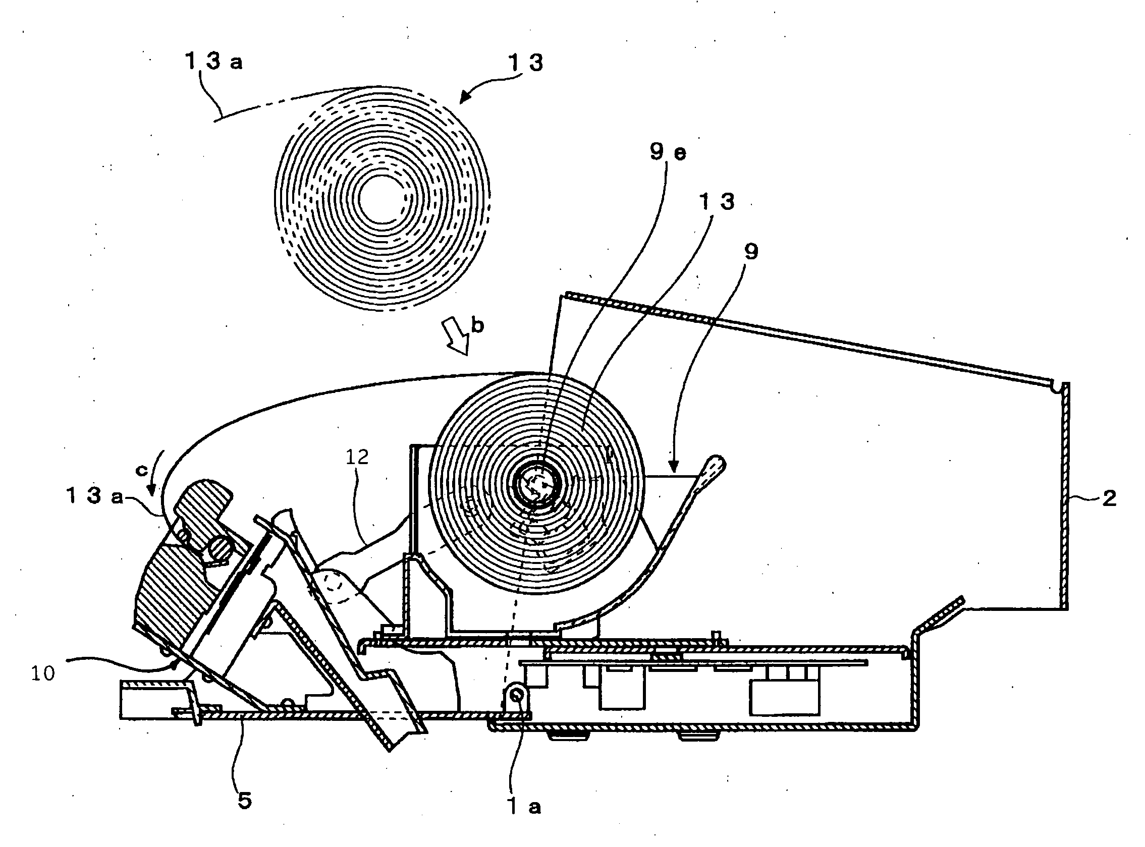
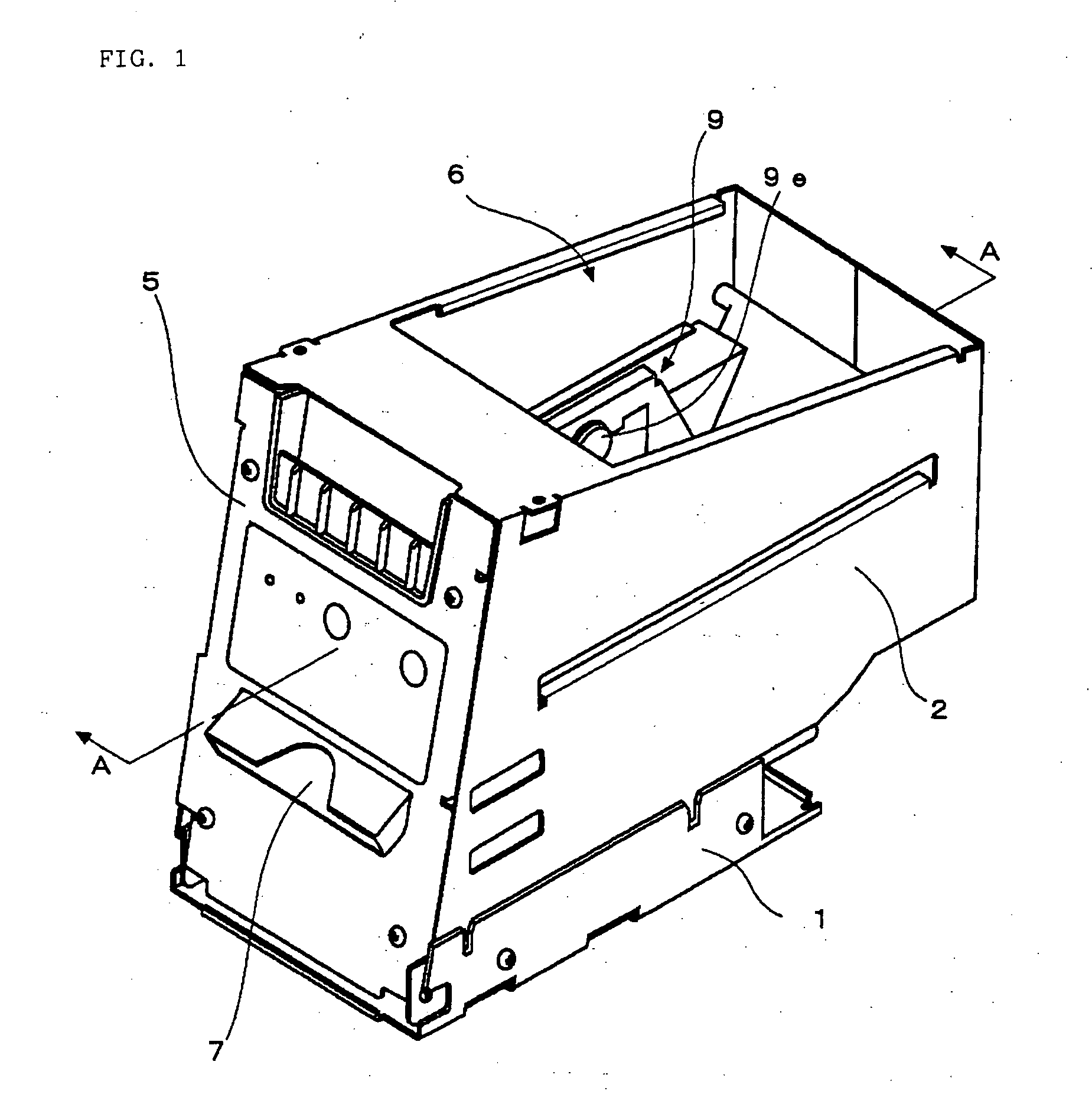
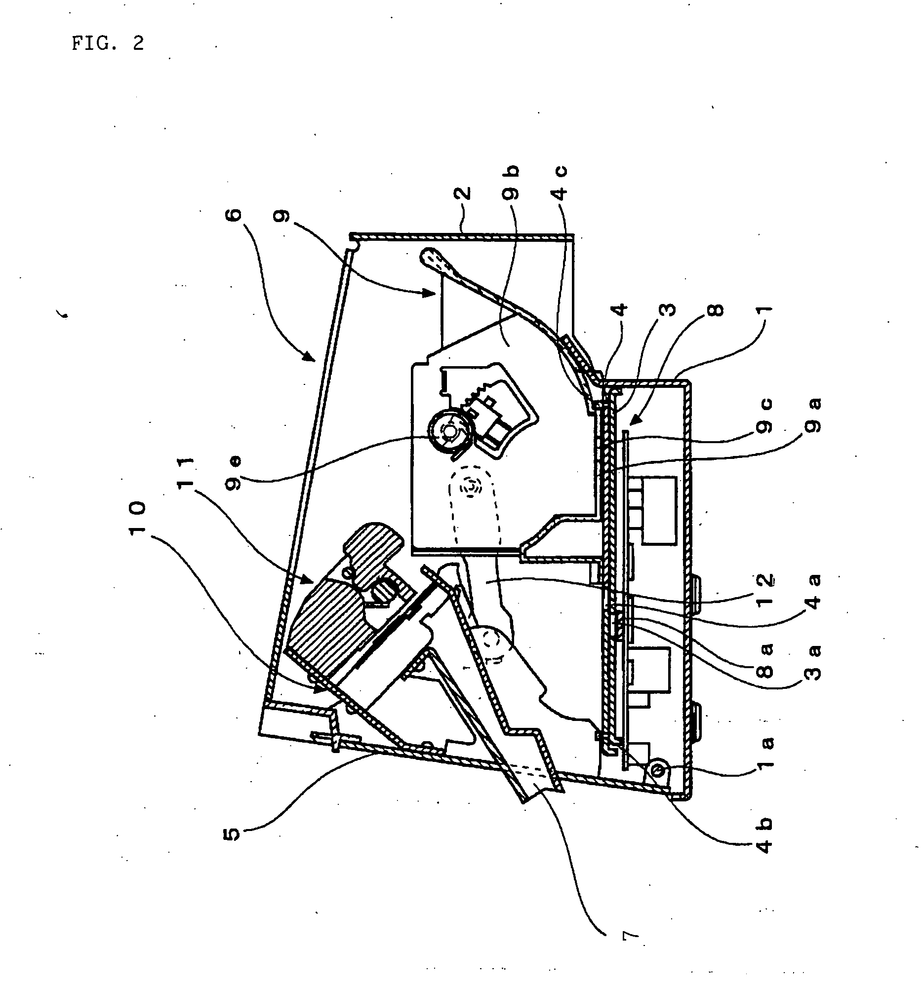
[0040] A printer according to the present invention prints and discharges a rolled printing paper. It comprises a frame, front panel, print unit, paper cutting unit, and paper holder unit. The frame partially covers the bottom, side, rear, and top surfaces of the printer. The front panel is swingably attached to the front face of the frame and has a paper exit through which the printed paper is discharged. The print unit is attached to the rear surface of the front panel and serves to print the printing paper. The paper cutting unit is attached to the rear surface of the front panel and serves to cut the printed paper. The paper holder unit is mounted for longitudinal movement in the frame and coupled to the front panel by a link, serving to hold the printing paper. If the front panel is opened, the print unit, paper cutting unit, and paper holder unit get out of the frame through its front surface.

[0041] The paper holder unit is formed of a bottom plate and side plates such that t...


PUM


Abstract

In a printer for printing a rolled printing paper, a front panel is attached to a frame that houses a print unit and a paper holder unit. When the front panel is opened, the print unit and the paper holder unit project on the front side of the frame in association with the action of the front panel.

Description

BACKGROUND OF THE INVENTION [0001] 1. Field of the Invention [0002] The present invention relates to a printer in which printing paper can be loaded and replaced with ease. [0003] 2. Description of the Related Art [0004] Some known printers are incorporated in various in- and outdoor vending machines and the like and used to issue recorded papers, receipts, tickets, etc. One such printer is described in Japanese Patent Application Laid-Open No. 2002-154719. This conventional printer will now be described with reference to FIGS. 15 and 16. [0005] In replacing a printing paper 150 with a new one, the upper end portion of a unit mounting section 144b that forms a front surface of a body bracket 144 shown in FIG. 15 is pulled in the direction indicated by arrow P (counterclockwise direction). Thereupon, the body bracket 144 is swung around a pivot shaft 148 and moved to the position of FIG. 16. When the body bracket 144 is in the state of FIG. 16, holding members 151 for a rolled paper ...

Claims


Application Information

Patent Timeline
IPC IPC(8): B41J15/00
CPCB41J15/042B41J11/70
Inventor SAKAINO, TSUYOSHIMIURA, SUMIO
Owner CITIZEN WATCH CO LTD
Learn More