A rotary stamping die

A technology for stamping dies and templates, applied in forming tools, manufacturing tools, metal processing equipment, etc., can solve the problems of rotation angle fixed mold and movable mold matching errors, high precision requirements and manufacturing costs, and increase the labor intensity of operators. Achieve the effect of extending processing time, increasing processing time and reducing maintenance time

Active Publication Date: 2016-02-10
NINGHAI RUIXIN MOLD
View PDF9 Cites 3 Cited by
  • Summary
  • Abstract
  • Description
  • Claims
  • Application Information

AI Technical Summary

Problems solved by technology

[0003] However, since the rotary stamping die needs to be continuously rotated at a certain angle to complete the stamping, the error in the rotation angle will directly lead to the coordination error between the fixed die and the movable die, and in severe cases, it will cause knife collision, which will damage the die
For stamping dies, the punch part is the most important part in the die, and its precision requirements and manufacturing costs are relatively high.
In the existing technology, the rotation angle error of the mold is often controlled through regular debugging, thereby reducing the situation of knife collision, but this not only greatly increases the labor intensity of the operator and reduces the processing efficiency, but also causes errors in the control program and slippage of the transmission parts. In the event of various emergencies such as dislocation, it is still impossible to avoid the situation that the tool will be damaged and the mold will be damaged.

Method used


Image

  • A rotary stamping die
  • A rotary stamping die
  • A rotary stamping die

Examples


Embodiment Construction

[0016] The present invention will be further described below in conjunction with the accompanying drawings and specific embodiments.

[0017] The above, upper end, lower end, and lower end described below all refer to the positional relationship in the direction of gravity.

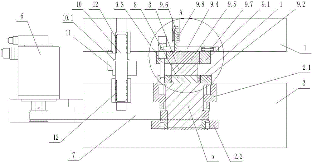
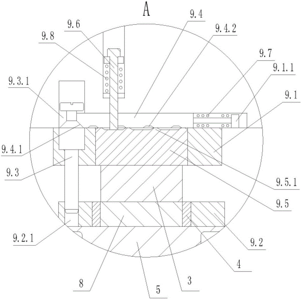
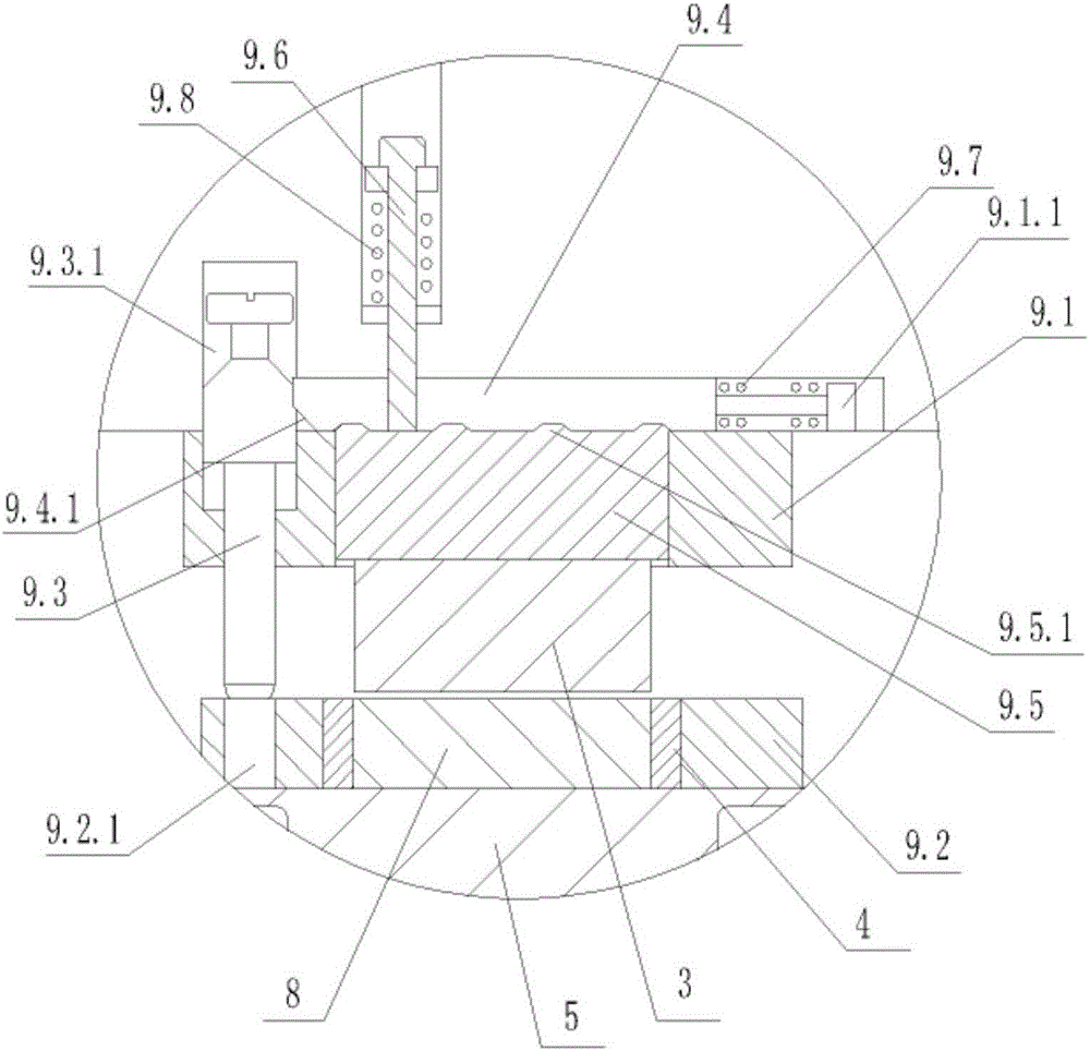
[0018] As shown in the figure, the present invention provides a rotary stamping die, which includes an upper template 1, a lower template 2, an upper module 3 and a lower module 4 for stamping products 8 between the upper template 1 and the lower template 2, and Set on the lower template 2 to drive the rotating shaft 5 of the lower module 4 to rotate, the product 8 is arranged in the mold cavity in the lower module 4, the upper module 3 is fixed to the lower end surface of the upper template 1, and the lower module 4 and One end of the rotating shaft 5 near the upper module 3 is fixed, that is to say, the lower module 4 is fixed to the upper end of the rotating shaft 5 . The rotating shaft 5 is rotatably...


PUM


Abstract

The invention discloses a rotary stamping die which comprises an upper die plate (1), a lower die plate (2), an upper die block (3), a lower die block (4) and a rotary shaft (5). The upper die block (3) and the lower die block (4) which are used for stamping a product (8) are arranged between the upper die plate (1) and the lower die plate (2), and the rotary shaft (5) which is used for driving the lower die block (4) to rotate is arranged on the lower die plate (2), is rotationally matched with the lower die plate (2) and is connected with an output shaft of an external motor (6) by a belt (7). The rotary stamping die is characterized in that an anti-collision mechanism which is used for preventing the upper die block (3) and the lower die block (4) from being collided with each other is arranged between the upper die plate (1) and the lower die plate (2). The rotary stamping die has the advantages that tool collision of the die can be prevented under emergency conditions, and accordingly operators do not need to frequently stop machines to maintain the rotary stamping die.

Description

technical field [0001] The invention relates to the technical field of stamping dies, in particular to a rotary stamping die. Background technique [0002] Among the existing stamping dies, there is a rotary stamping die. Its working principle is to rotate the fixed die according to the beat, so that the movable die can continuously stamp out the required models at different positions of the fixed die to meet the requirements of multiple positions on the product. stamping needs. Especially for products that are evenly distributed in the circumferential direction, the same model can be punched out in the circumferential direction of the product only by rotating around the axis of the fixed die, which not only reduces the number of die punches and simplifies the die structure, but also relies on the same punch Complete the entire stamping process, so the consistency of each part of the stamped product is high. [0003] However, since the rotary stamping die needs to be conti...

Claims


Application Information

Patent Timeline
Patent Type & Authority Patents(China)
IPC IPC(8): B21D37/10B21D22/14
Inventor 万夏军严卫军
Owner NINGHAI RUIXIN MOLD
Why Eureka
Try Eureka