Anntena for radio base station and radio communication system
a radio base station and radio communication technology, applied in the direction of substation equipment, radio transmission, transmission, etc., can solve the problems of short length of the antenna at the base station, radio station becomes impossible to make a sure reception, and the transmission loss per unit length is increased, so as to achieve the effect of widening the radio communication range of the radio base station
- Summary
- Abstract
- Description
- Claims
- Application Information
AI Technical Summary
Benefits of technology
Problems solved by technology
Method used
Image

Examples
first embodiment
[0021] A first embodiment will set forth an antenna for a radio base station.
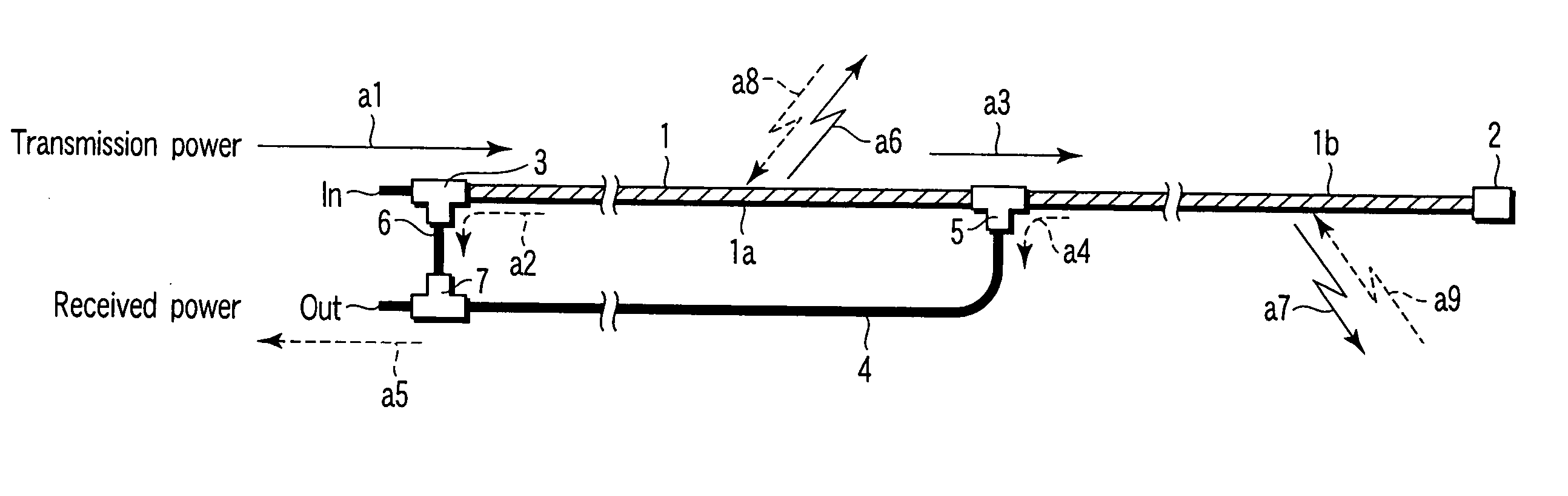
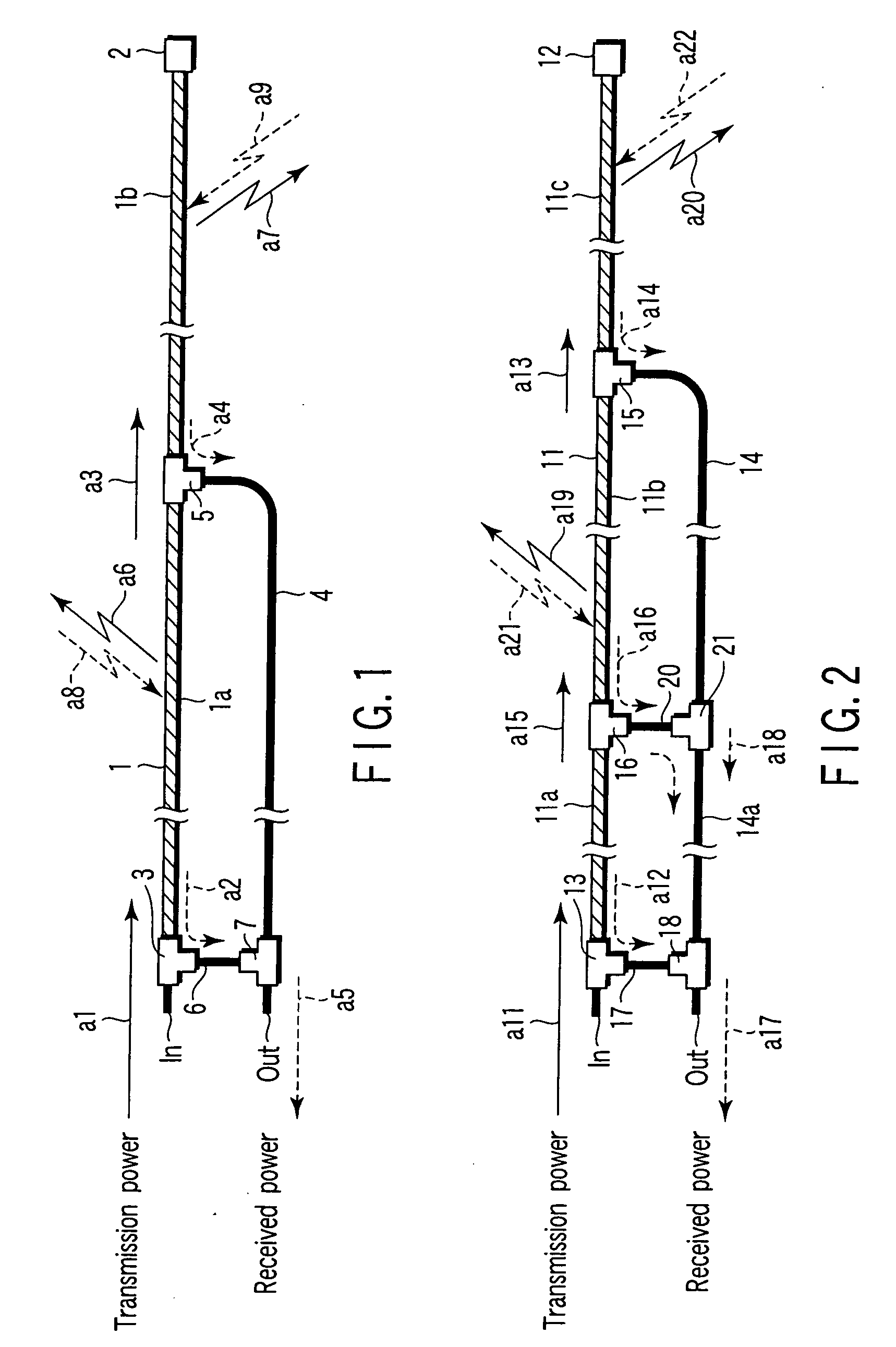
[0022] In FIG. 1, a leaky coaxial cable 1 constitutes a leaky transmission line. The transmission line may be constituted by something other than a leaky coaxial cable.
[0023] For example, the transmission line may be constituted by an open coaxial cable.
[0024] The coaxial cable 1 inputs transmission power from an input terminal IN to transmit it toward a terminator 2. The coaxial cable 1 transmits received power received from the outside toward the input terminal IN.
[0025] The coaxial cable 1 disposes a first directional coupler 3 near the input terminal IN.
[0026] The coupler 3 has a function to pass the transmission power advancing from the input terminal IN to the terminator 2 as shown by an arrow a1 of a solid line in the figure and a function to output the received power received from the outside and advanced to the input terminal IN to a below-mentioned power compositor as shown by an arrow a2 of ...
second embodiment
[0048] The antenna for the radio base station will be described in accordance with the second embodiment.
[0049] In FIG. 2, a leaky coaxial cable 11 constitutes a leaky transmission line. The transmission line may be constituted by a cable other than a coaxial cable.
[0050] The coaxial cable 11 inputs transmission power from an input terminal IN to transmit it toward a terminator 12. The coaxial cable 11 transmits received power received from the outside toward the input terminal IN.
[0051] The coaxial cable 11 disposes a first directional coupler 13 at a side of the input terminal IN.
[0052] The first coupler 13 has a function to pass the transmission power advancing from the input terminal IN to the terminator 12 as shown by an arrow all of a solid line in the figure and a function to output the received power received from the outside and advanced toward the input terminal IN to a below-mentioned power compositor as shown by an arrow a12 of a dot line in the figure.
[0053] Furthe...
third embodiment
[0084] A radio communication system will be described in a third embodiment.
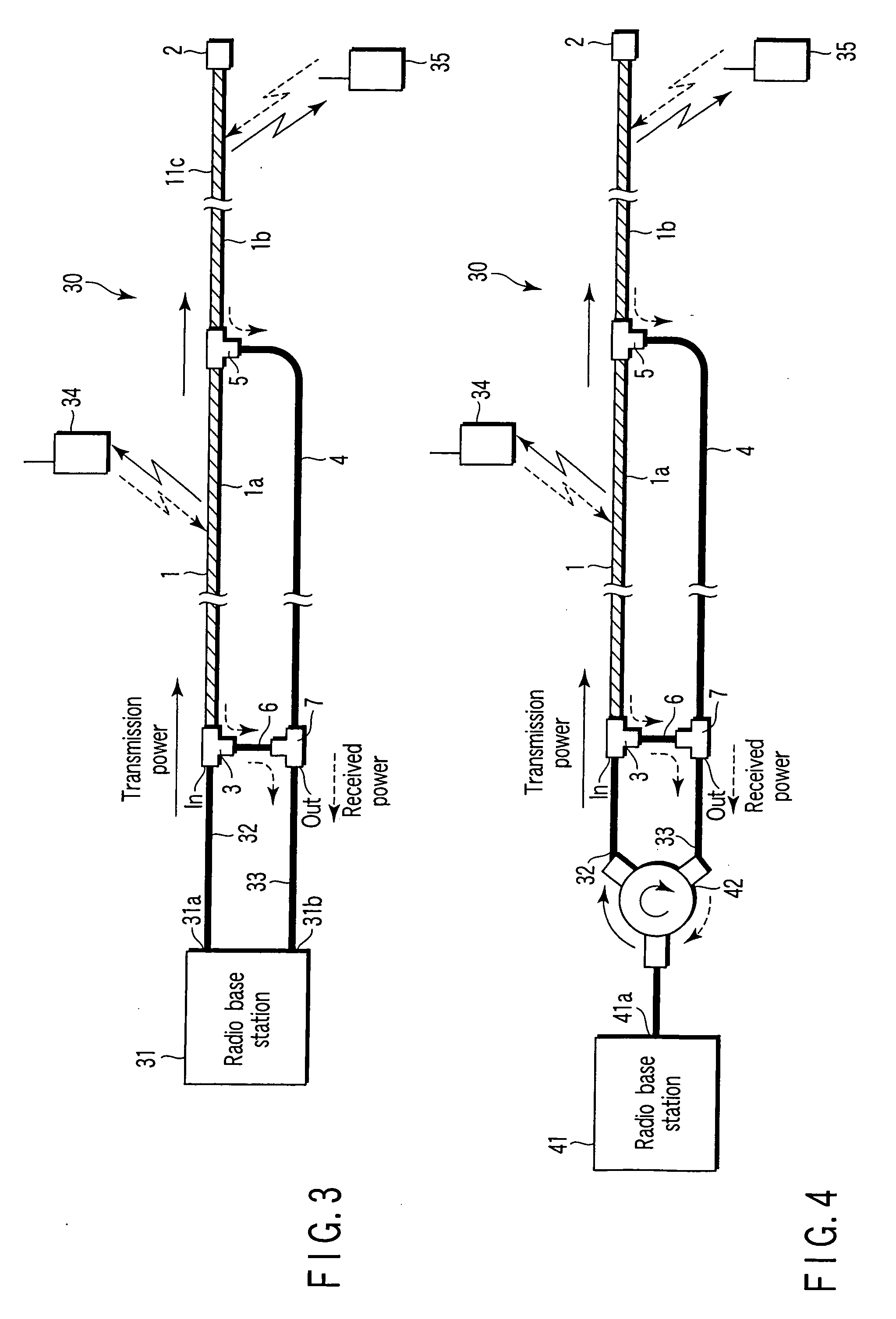
[0085] In FIG. 3, a radio base station 31 has a transmitting antenna terminal 31a and a receiving antenna terminal 31b.
[0086] The base station 31 connects the antenna terminal 31a with an input terminal IN of an antenna 30 a radio base station via a coaxial cable 32 and also connects the antenna terminal 31b with an output terminal OUT of the antenna 30 via a coaxial cable 33.
[0087] The antenna 30 has the same structure as that of the aforementioned first embodiment and composed of the leaky coaxial cable 1, terminator 2, first directional coupler 3, low-loss coaxial cable 4, second directional coupler 5, coaxial cable 6 and power compositor 7.
[0088] Radio terminal devices 34 and 35 are disposed around the coaxial cable 1. That is, the terminal device 34 is disposed around the section 1a of the coaxial cable 1. The radio terminal 35 is disposed around the section 1b of the coaxial cable 1.
[0089] In this...
PUM
 Abstract
Description
Claims
Application Information
 - R&D
- Intellectual Property
- Life Sciences
- Materials
- Tech Scout
- Unparalleled Data Quality
- Higher Quality Content
- 60% Fewer Hallucinations
Browse by: Latest US Patents, China's latest patents, Technical Efficacy Thesaurus, Application Domain, Technology Topic, Popular Technical Reports.
© 2025 PatSnap. All rights reserved.Legal|Privacy policy|Modern Slavery Act Transparency Statement|Sitemap|About US| Contact US: help@patsnap.com