Natural smoke/fog distribution system

a distribution system and natural smoke technology, applied in the field of smoke machines, can solve the problems of rapid rise, spread and dissipation, and the effect of leaving the effect of the original

Inactive Publication Date: 2007-01-18
SCHOCK WILLIAM R
View PDF5 Cites 3 Cited by
  • Summary
  • Abstract
  • Description
  • Claims
  • Application Information

AI Technical Summary

Benefits of technology

[0006] A method for use with a Cold Fog Generator and / or Natural Smoke / Fog Distribution System (cfgnsfds) comprising the steps of: (a) injecting expanding smoke into an inlet orifice utilizing a venturi effect to foster the full expansion of smoke once inside chamber, thereby (b) introducing smoke into an expansion chamber that will complete its expansion process, (c) building air pressure within expansion chamber and thereby harnessing natural energy from expanding gases to then (d) force said smoke through an ice mass thereby (e) cooling the smoke and creating fog, then (f) forcing fog / smoke out of cfgnsfds via an exhaust duct and out to desired location.
[0007] In another preferred method the steps are as follows: (a) injecting expanding smoke into an inlet orifice utilizing a venturi effect to foster the full expansion of smoke once inside chamber, thereby (b) introducing smoke into an expansion chamber that will complete its expansion process, (c) building air pressure within expansion chamber and thereby harnessing natural energy from expanding gases to then (d) force fog / smoke out of cfgnsfds via an exhaust duct and out to desired location.

Problems solved by technology

If the hot smoke is not cooled significantly, it will rise, spread and dissipate.
However, since smoke producing machines produce smoke at around 165°-200°, it quickly rises and dissipates if left unchanged.

Method used


Image

  • Natural smoke/fog distribution system
  • Natural smoke/fog distribution system
  • Natural smoke/fog distribution system

Examples


Embodiment Construction

[0019] According to a preferred embodiment of the present invention, a unique system, method, and apparatus is used to deliver a cold and low-lying fog effect. The present invention is described in enabling detail below.

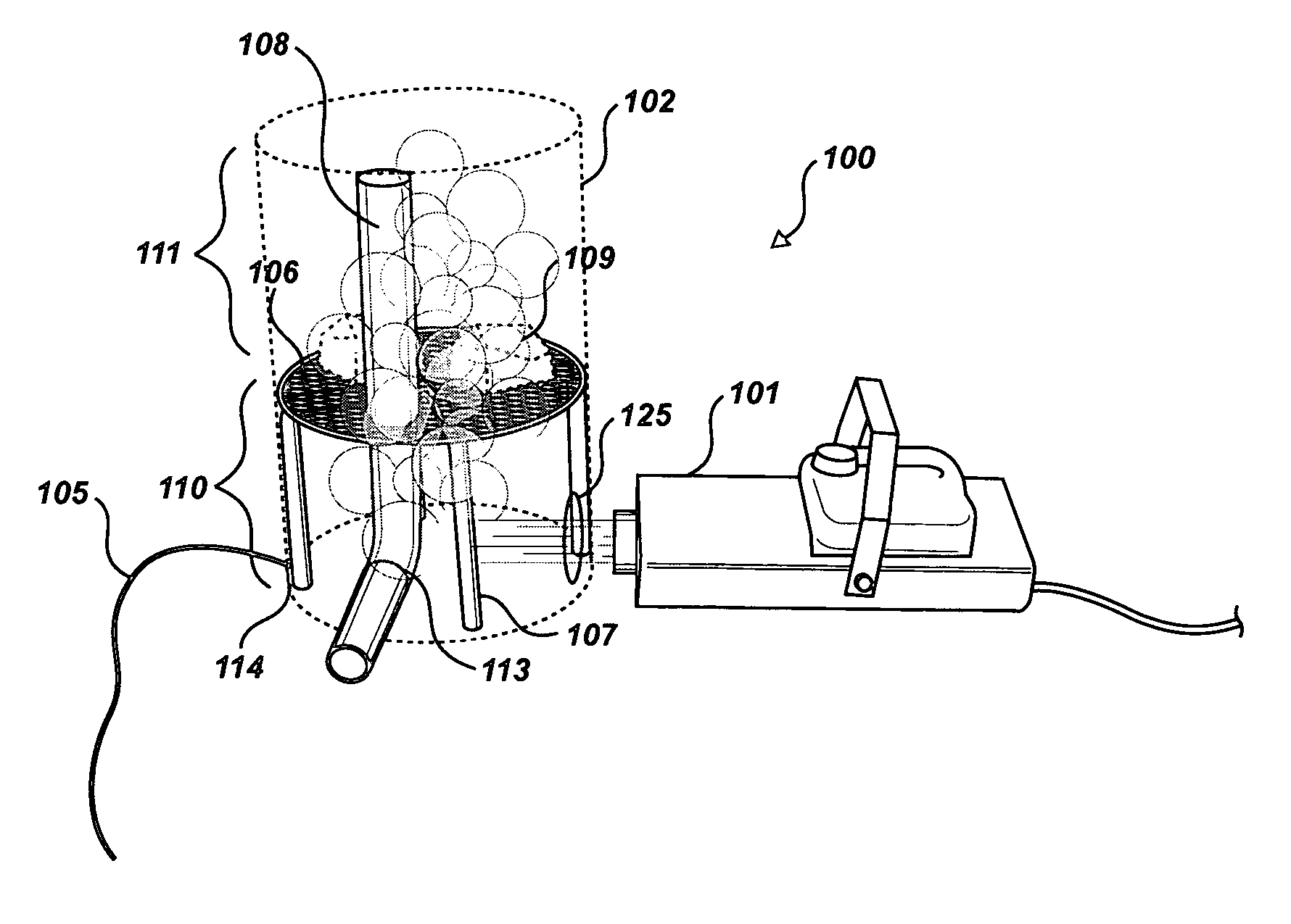
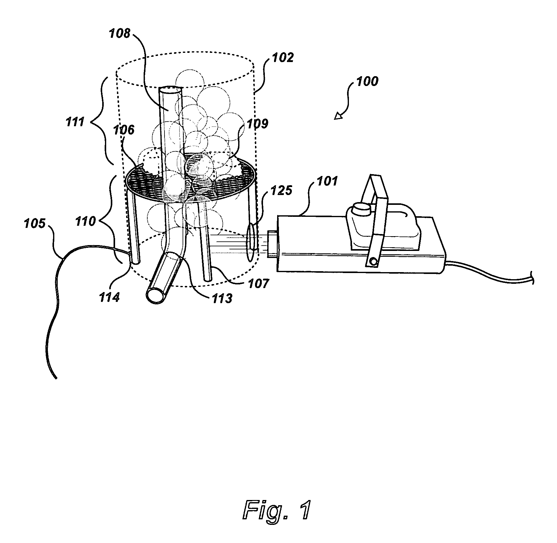
[0020]FIG. 1 is a perspective view of a preferred embodiment of the present invention. Cold fog generator and smoke / fog distribution system 100 (hereafter cfgds) comprises a smoke machine 101, a chamber 102, an inlet orifice 125, (or in some preferred embodiments a one-way venturi 103 as illustrated in FIG. 11), and tubing 105. FIG. 2 illustrates the remaining elements: an ice tray 106, support apparatus 107, exhaust duct 108, ice 109, expansion chamber 110 and flash freeze chamber 111.

[0021] It should be pointed out here that cfgnsfds 100 in some preferred embodiments is a sealed system. In other preferred embodiments, cfgnsfds 100 is a semi-sealed system. Although cfgnsfds 100 possesses orifices, it is to be understood that the mentioning of these orifices is for...


PUM


Abstract

A method for use with a cold fog generator and/or smoke/fog distribution system comprising the steps of: (a) injecting expanding smoke into an inlet orifice utilizing a venturi effect to foster the full expansion of smoke once inside chamber, thereby (b) introducing smoke into an expansion chamber that will complete its expansion process, (c) building air pressure within expansion chamber and thereby harnessing natural energy from expanding gases to then (d) force said smoke through an ice mass thereby (e) cooling the smoke and creating fog, then (f) forcing fog/smoke out of cfgnsfds via an exhaust duct. In another preferred method the steps are as follows: (a) injecting expanding smoke into an inlet orifice utilizing a venturi effect to foster the full expansion of smoke once inside chamber, thereby (b) introducing smoke into an expansion chamber that will complete its expansion process, (c) building air pressure within expansion chamber and thereby harnessing natural energy from expanding gases to then (d) force fog/smoke out of cfgnsfds via an exhaust duct.

Description

CROSS-REFERENCE TO RELATED APPLICATIONS [0001] A COLD FOG GENERATOR AND / OR NATURAL SMOKE / FOG DISTRIBUTION SYSTEM; [0002] A ONE WAY VENTURI FOR USE WITH A COLD FOG GENERATOR AND / OR NATURAL SMOKE / FOG DISTRIBUTION SYSTEM FIELD OF THE INVENTION [0003] The present invention is in the area of smoke machines and pertains more particularly to methods, apparatus, and systems for generating fog, flash freezing smoke and disbursing both to a remote location. BACKGROUND OF THE INVENTION [0004] Many entertainment events and other uses for smoke call for a heavy, thick, and low-lying fog effect. In order to produce a low-lying fog effect from a fluid smoke machine which will roll low over the ground, the smoke must be cooled significantly. If the hot smoke is not cooled significantly, it will rise, spread and dissipate. However, since smoke producing machines produce smoke at around 165°-200°, it quickly rises and dissipates if left unchanged. [0005] Therefore, what is clearly needed in the art i...

Claims


Application Information

Patent Timeline
Patent Type & Authority Applications(United States)
IPC IPC(8): F25D3/02
CPCF41H9/06
Inventor SCHOCK, WILLIAM
Owner SCHOCK WILLIAM R
Why Eureka
Try Eureka