Working cylinder with terminal position damping

Inactive Publication Date: 2007-01-18
NORGREN GMBH
View PDF8 Cites 5 Cited by
  • Summary
  • Abstract
  • Description
  • Claims
  • Application Information

AI Technical Summary

Benefits of technology

[0004] It is therefore the object of the invention to create a working cylinder with end position damping whose damping device is distinguished by a simple, operationally reliable construction and which, with a limited installed length of the entire working cylinder, has a long damping stroke.
[0006] Of the two damping elements that are insertable into one another upon the approach of the piston to its end position, as least one is supported for limited longitudinal displacement on the end part or the piston between two axially spaced-apart terminal positions with respect to the piston or the end part as applicable. Both damping elements are provided with cooperating inhibiting means, under whose influence the longitudinally displaceable damping element, upon a movement of the piston away from its end position, is adjustable into a terminal position, which is farther away from the piston than a first terminal position that the damping element normally assumes. The displaceability of the one damping element relative the piston or the end part produces an additional damping stroke by a telescoping action of the parts sliding in one another upon the approach of the piston to its end position. The inhibiting means assure that upon the motion of the piton away from its end position, the longitudinally displaceable damping element returns to its outset position without requiring additional actuation devices, such as spring elements or the like, for doing so. Hence no additional installation space is needed. The simple construction moreover allows the use of parts produced on a near-mass- production basis even for long damping strokes, that is, long damping paths.

Problems solved by technology

Since the installed length of a working cylinder is often predetermined, for instance by standards, for a given piston stroke, the damping stroke cannot be made arbitrarily long.
Although this working cylinder does have a longer damping path or stroke in comparison to the aforementioned prior art, nevertheless the cone spring requires additional installation space, which is in addition to the fact that the use of spring elements, because of their limited service life, is problematic in many applications.

Method used


Image

  • Working cylinder with terminal position damping
  • Working cylinder with terminal position damping
  • Working cylinder with terminal position damping

Examples


Embodiment Construction

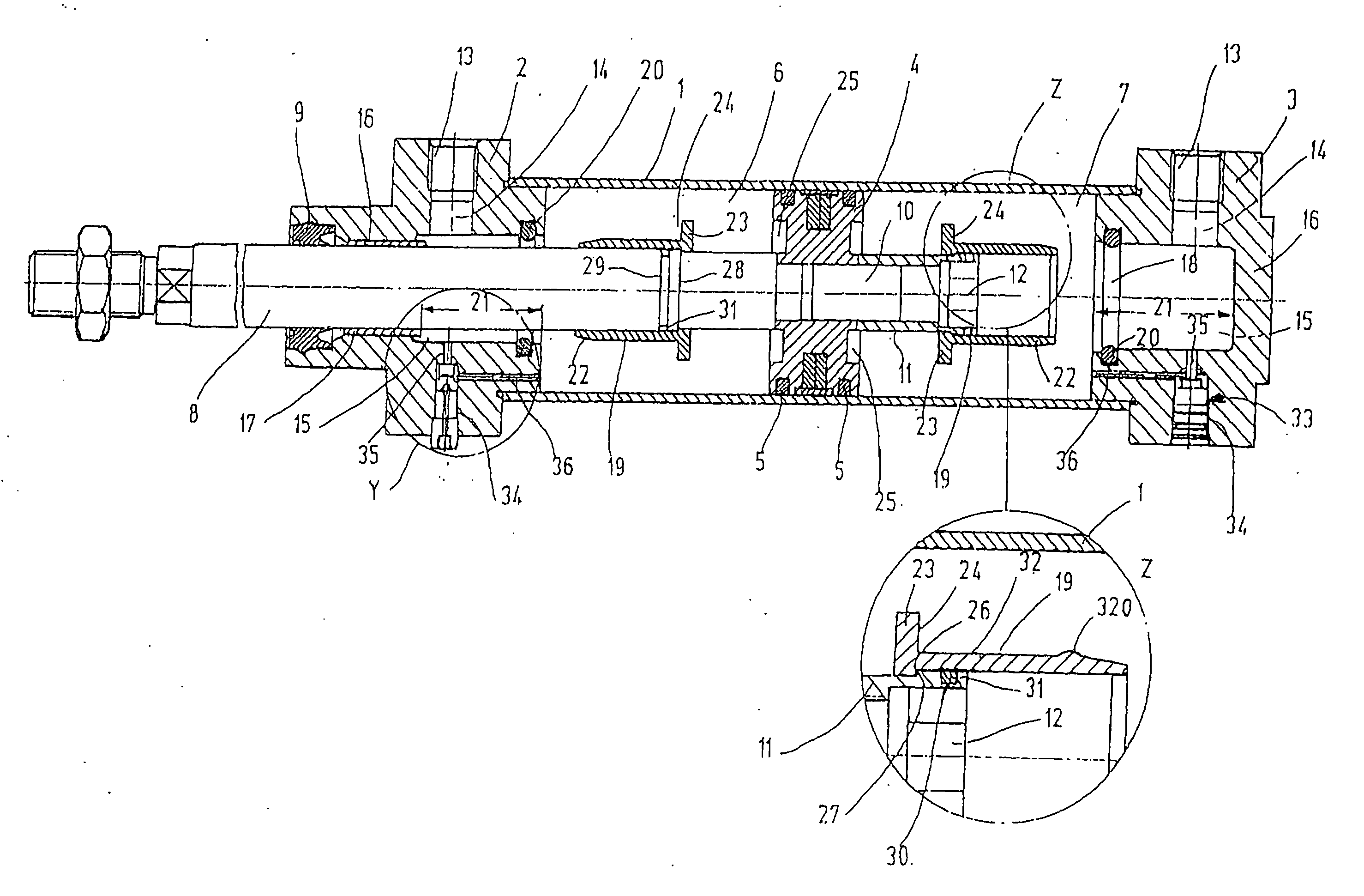
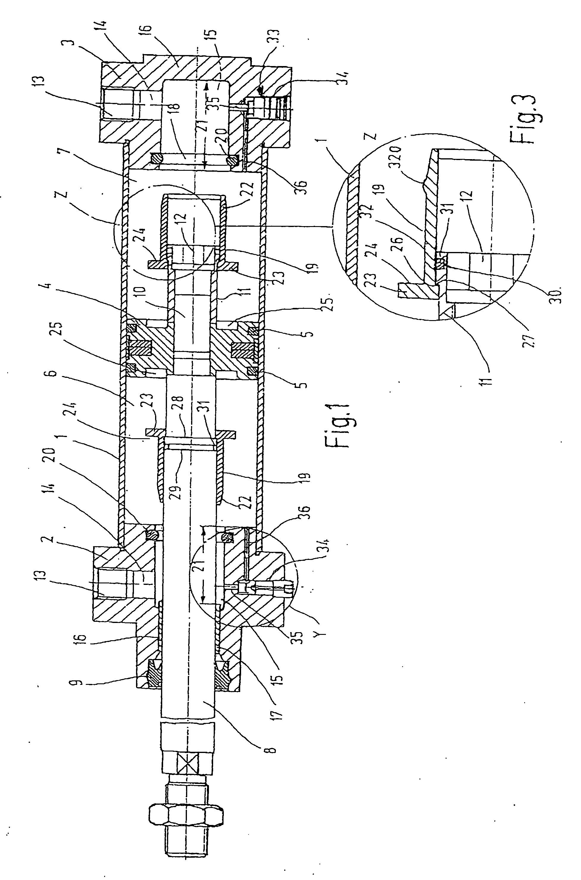
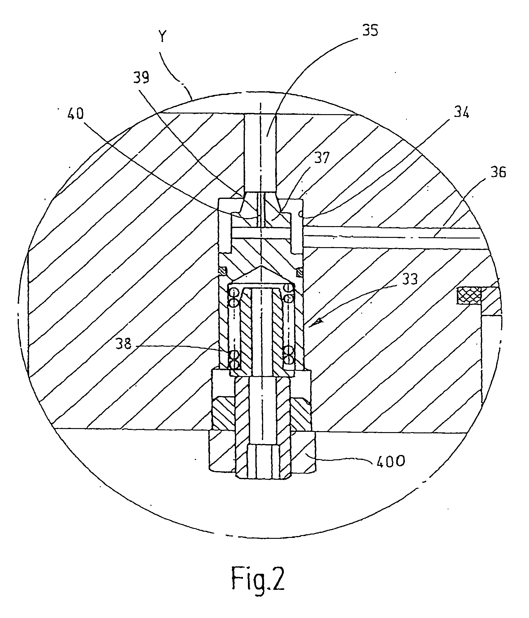
[0018] Referring now more particularly to FIGS. 1-7 of the drawings, there is shown an illustrative working cylinder in accordance with the invention, which is in the form of a pneumatic cylinder having a cylinder body in the form of a cylindrical tube 1 and two end parts 2, 3 connected to the cylindrical tube 1 in a sealed fashion. The cylindrical tube 1 surrounds a cylinder chamber in which a piston 4, which is sealed off from the inner wall of the cylindrical tube 1 via piston ring seals, is longitudinally displaceably. The piston 4 divides the cylinder chamber into two cylinder or pressure compartments 6, 7, which are separated by the piston 4.

[0019] A coaxial cylindrical piston rod 8 is fixed to the piston 4 and is guided through the end part 2 in sealed fashion. A piston rod seal is shown at 9. The piston rod 8 that crosses through the cylinder compartment 6 is lengthened on the diametrically opposite side of the piston. On its lengthened portion 10, a coaxial cylindrical bus...


PUM


Abstract

A working cylinder with end position damping which has at least one telescoping damping pin, which upon the approach to the corresponding end position of the piston plunges into a receiving opening, which closes off a damping chamber and forms a damping element, in an end part of the working cylinder or in the piston.

Description

FIELD OF THE INVENTION [0001] The invention relates to a working cylinder with end position damping, which has a cylinder body that contains a cylinder chamber, the cylinder body for instance being in the form of a tube or an extruded profile section; two end parts that close the cylinder on its ends; a piston supported longitudinally displaceably in the cylinder chamber between two end positions; and a device for damping the motion of the piston upon the approach to a at least one of its end positions. BACKGROUND OF THE INVENTION [0002] Pressure medium-actuated working cylinders often have end position damping to assure impact-free working action of the working cylinder. One example of such a pressure medium-actuated working cylinder with end position damping is described in U.S. Pat. No. 6,758,127. In this working cylinder, an axially protruding, tubular, cylindrical damping pin is provided on each of the two face ends of the piston, and associated with the damping pin is a receiv...

Claims


Application Information

Patent Timeline
IPC IPC(8): F16F9/36
CPCF15B15/222F15B15/082
Inventor RIEDEL, RALPH
Owner NORGREN GMBH
Why Eureka
Try Eureka