Sewing machine

Inactive Publication Date: 2007-05-31
SAHL JOHANNES
View PDF5 Cites 0 Cited by
  • Summary
  • Abstract
  • Description
  • Claims
  • Application Information

AI Technical Summary

Benefits of technology

[0003] The invention is thus based on the object of providing a sewing machine of the kind mentioned above in such a way that a comparatively simple and operationally reliable construction is obtained.
[0005] Since as a result of these measures the one on the driven side of the two mutually combing gearwheels is rotated back and forth via a fixed link about the axis of the gearwheel on the drive side, the rotation caused by the rotation of the fixed link overlaps the gearwheel on the driven side with the effect that the gearwheel on the driven side is driven periodically with overfeed and underfeed, which in the case of a respective configuration of the lever and transmission ratios leads to the demanded intermittent forward feed of the garment, without having to take into account the disadvantages linked to the use of a belt drive with an excessively long belt. It is merely necessary to ensure a respective throw of the fixed link connecting the two toothed wheels. This can easily be achieved by means of the control lever acting upon the fixed link.

Problems solved by technology

The disadvantageous aspect in this known forward feeding system for garments is however that as a result of the transversal displacement of the belt strands between the two gearwheels a comparatively complex construction is required leading to an additional load on the belt.

Method used


Image

  • Sewing machine
  • Sewing machine
  • Sewing machine

Examples


Embodiment Construction

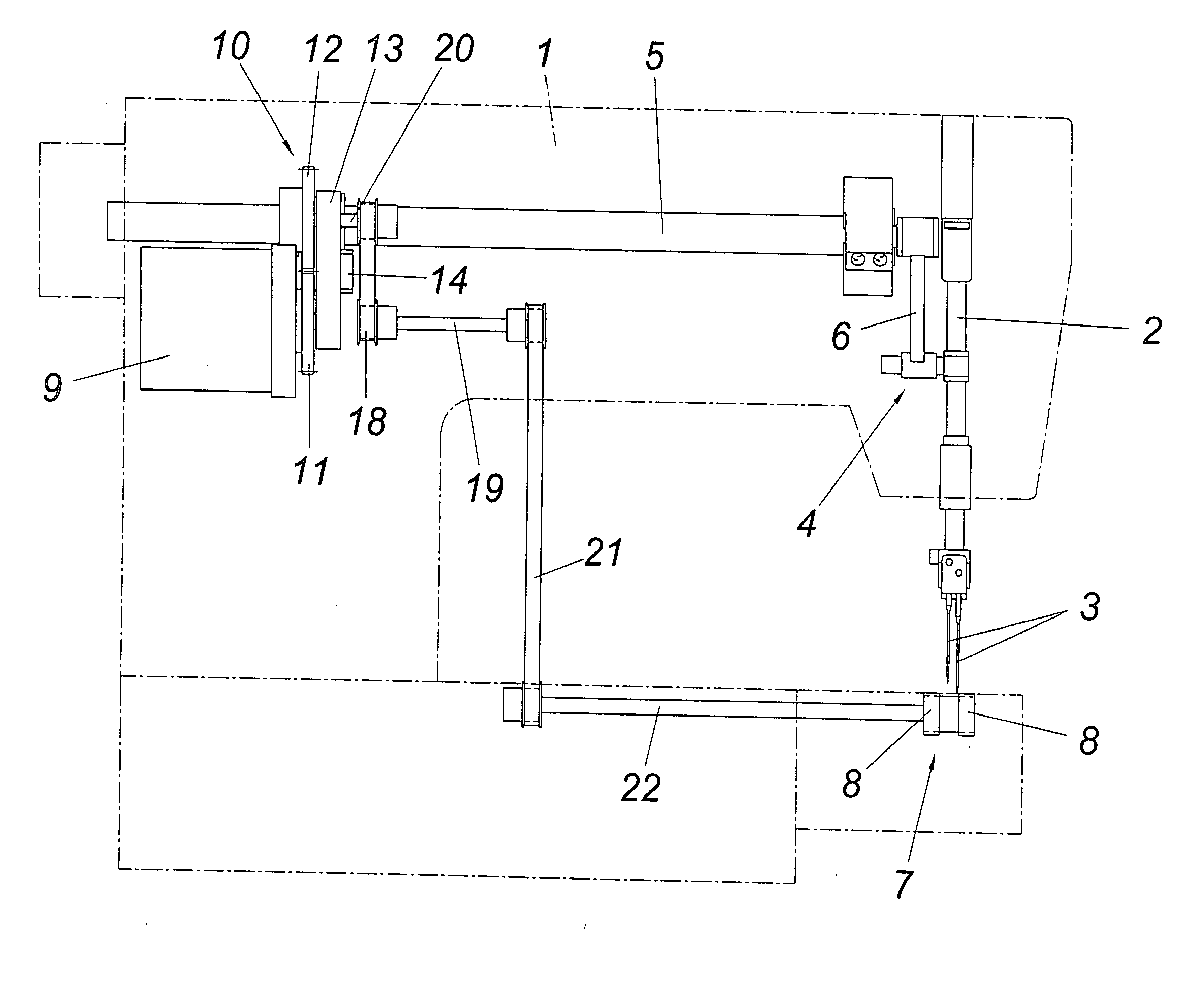
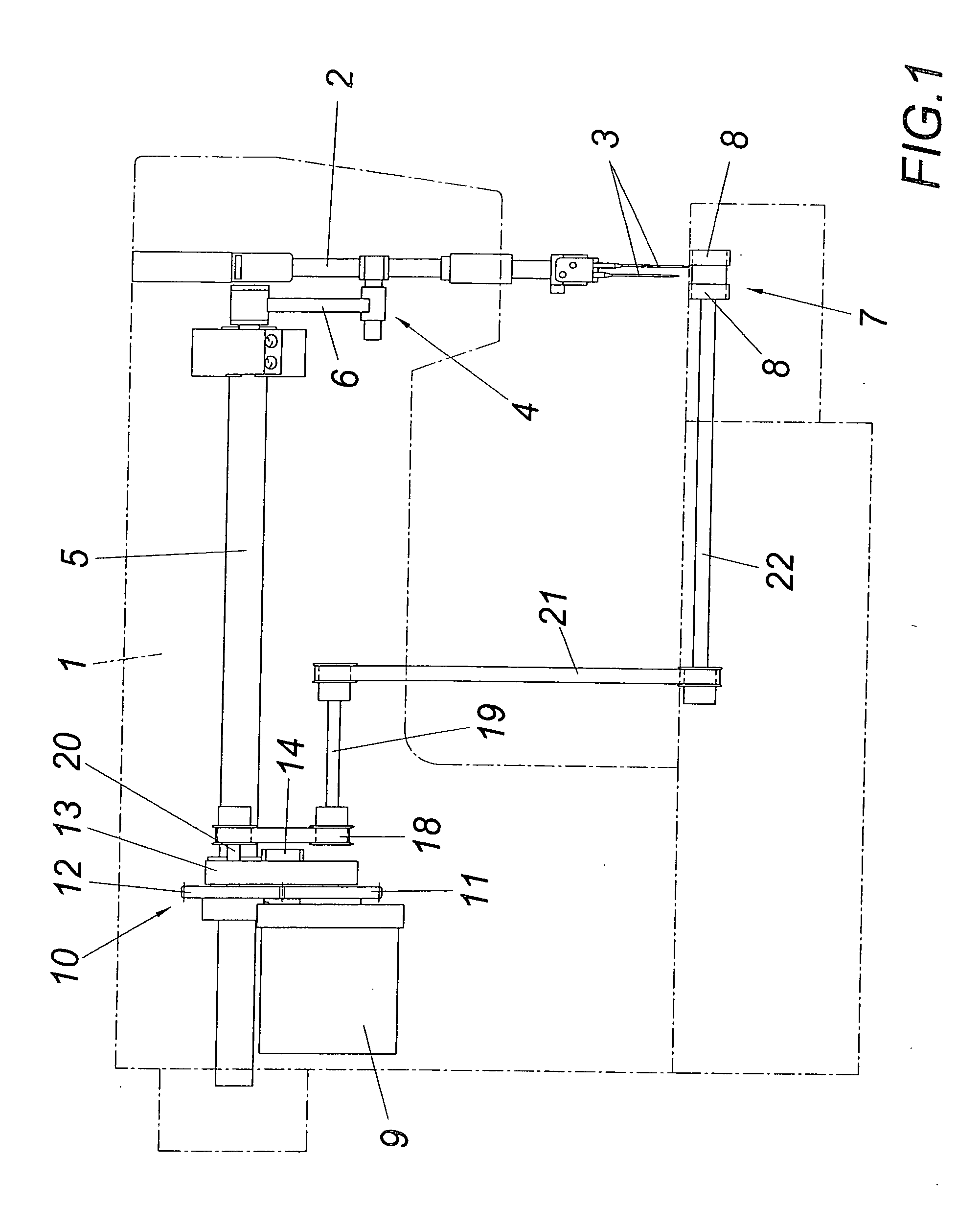
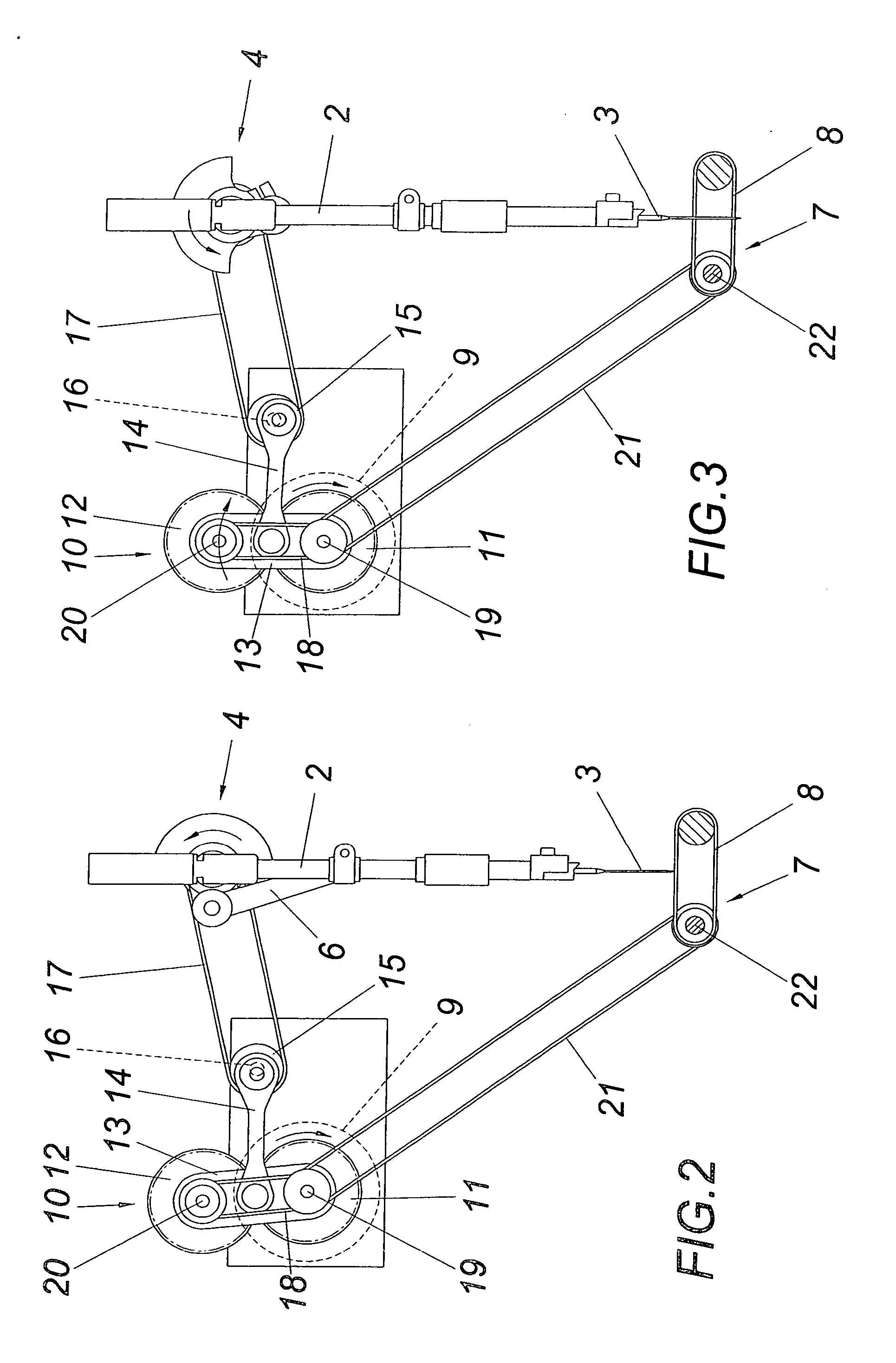
[0012] The sewing machine 1, which is only indicated with the dot-dash line, comprises a needle bar 2 for receiving sewing needles 3 and a sewing needle drive 4 which consists of a drive shaft 5 and a crank mechanism 6 which acts upon the needle bar 2. A belt conveyor 7 is provided for the forward feed of the garment, which conveyor is composed of two parallel conveyor belts 8 between which the needles 3 penetrate the garment. The drive for the belt conveyor 7 is derived from a continuous rotational drive 9 which is preferably driven electrically and is arranged on a base plate. An intermediate drive 10 is driven by said rotational drive, which intermediate drive comprises two mutually combing gearwheels 11 and 12. While the gearwheel 11 on the driven side of the intermediate drive 10 is fixedly situated on the driven shaft of rotational drive 9, the gearwheel 12 on the driven side is rotatably held in a fixed link 13 which is held in a freely rotatable manner on the driven shaft of...


PUM


Abstract

A sewing machine is described with a sewing needle drive (4) and a forward feed drive for the garment, comprising a continuous rotational drive (9), a belt conveyor (7) for the garment and an intermediate drive (10) with two gearwheels disposed between the rotational drive (9) and the belt conveyor (7), of which the gearwheel on the driven side can be twisted relative to the one on the drive side with over-feed or underfeed by means of a control lever (14) driven by an eccentric drive (15) depending on the sewing needle drive (4). In order to provide advantageous construction conditions it is proposed that the two gearwheels are arranged as mutually combing gearwheels (11, 12), of which the one on the driven side is held in a fixed link (13) rotationally held about the axis of the gearwheel (11) on the drive side, on which the control lever (14) acts.

Description

1. FIELD OF THE INVENTION [0001] The invention relates to a sewing machine with a sewing needle drive and a forward feed drive for the garment, comprising a continuous rotational drive, a belt conveyor for the garment and an intermediate drive with two gearwheels disposed between the rotational drive and the belt conveyor, of which the gearwheel on the driven side can be twisted relative to the one on the drive side with overfeed or underfeed by means of a control lever driven by an eccentric drive depending on the sewing needle drive. 2. DESCRIPTION OF THE PRIOR ART [0002] In order to obtain an intermittent forward feed of the garment by a continuous rotational drive it is known (WO 98 / 15678 A1) to drive a belt drive via the continuous rotational drive with two stationary held gearwheels about which the belt arranged with excess length is guided. Two guide rollers are used for tensioning the belt, which rollers are arranged on a control lever arranged coaxially relative to a gearwh...

Claims


Application Information

Patent Timeline
IPC IPC(8): D05C15/00D05B27/10D05B27/14
CPCD05B27/10D05B27/14
Inventor SAHL, JOHANNES
Owner SAHL JOHANNES
Why Eureka
Try Eureka