Auto-eject foot stand assembly with multi-viewing angles

a technology of multi-viewing angle and foot stand, which is applied in the direction of portable computers, furniture parts, instruments, etc., can solve the problems of inconvenient head upwards or downwards movement, the viewing angle of the conventional pmp cannot be adjusted according to the viewer's, etc., to extend the endurance limit and enhance the spring force

Inactive Publication Date: 2007-01-18
THOMSON LICENSING SA
View PDF7 Cites 28 Cited by
  • Summary
  • Abstract
  • Description
  • Claims
  • Application Information

AI Technical Summary

Benefits of technology

[0007] In another embodiment, the locker has a first arm slightly extending upwards and a second arm substantially parallel to the second sidewall of the bracket, wherein the finger is formed on the second arm. A pin aperture is defined between the first arm and second arm. A barrel with a pin hole is formed in, the second sidewall of the bracket. A pin is inserted through the pin aperture and pin hole to pivotally mount the locker on the barrel. The pin hole has two lugs formed at a top edge thereof and welded with the pin for preventing the pin from escaping from the barrel.
[0008] Preferably, the metal spring plate has a lateral portion, an upright portion integrated with the lateral portion, and a tongue formed beneath the lateral portion and abutting the second arm of the locker. Advantageously, a pad cork is fitted in the metal spring plate between the inner surface of the tongue and inner surface of the housing in order to enhance the spring force and extend the endurance limit.

Problems solved by technology

However, the viewing angle of the conventional PMP can not be adjusted according to a viewer's desire when the PMP is disposed at a situation.
Thus, it is very inconvenient for a viewer to move his head upwards or downwards to find out the best viewing angle.

Method used


Image

  • Auto-eject foot stand assembly with multi-viewing angles
  • Auto-eject foot stand assembly with multi-viewing angles
  • Auto-eject foot stand assembly with multi-viewing angles

Examples


Embodiment Construction

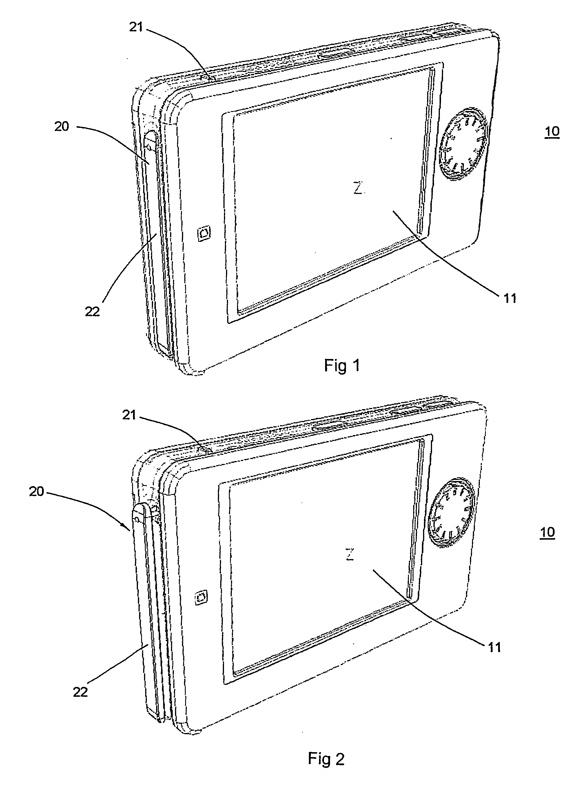
[0018] With reference to FIGS. 1-2, a personal media player 10 generally includes a housing (not numbered) with a display 11 provided in a front side thereof.

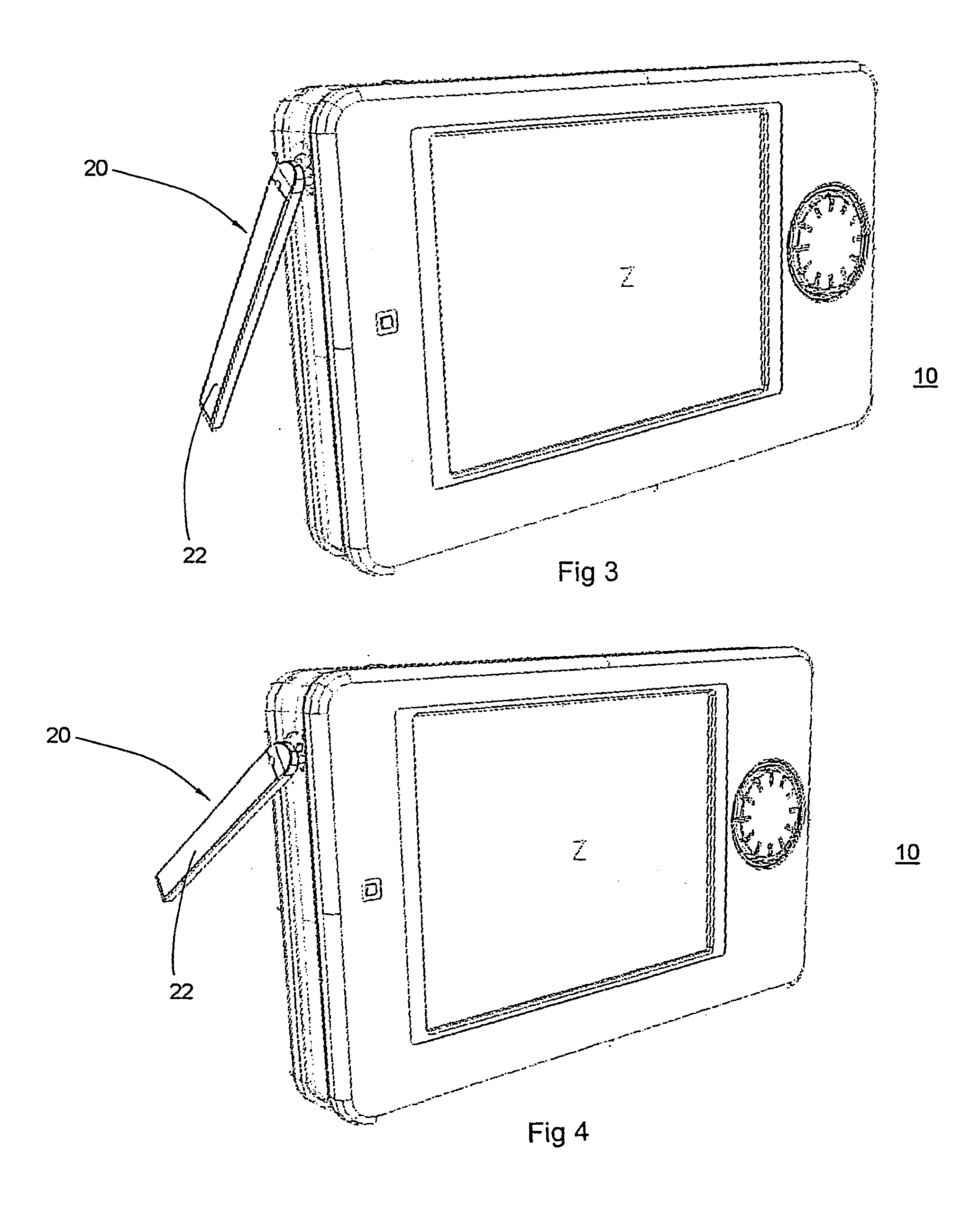
[0019] A foot stand assembly 20 in accordance with the present invention is installed at a left side of the personal media player 10. A button 21 is provided on the top side for operating the stand foot 20. When the button 21 is pressed down, a foot 22 of the foot stand assembly 20 can be automatically ejected out from a recess defined in the left side of the housing, as illustrated in FIG. 2. Then, the foot 22 can be rotated to support the PMP 10 with various viewing-angles, as illustrated in FIGS. 3-6.

[0020] With reference to FIGS. 7-9, an axle 23 extending perpendicular to the foot 22 is provided. A bracket 30 is mounted in the housing of the PMP 10 by means of plurality fasteners, and the axle 23 is rotatably mounted on the bracket 30.

[0021] The bracket 30 has a first sidewall 31 and a second sidewall 32, wherein the fir...


PUM


Abstract

An auto-eject foot stand assembly with multi-viewing angles for a visual device includes a foot having an axle perpendicular to the foot. The axle rotatably extends in a bracket. A gear is securely provided outside the axle and between the bracket and the foot. A spring is provided between the gear and the bracket. An elasticity plate is engaged with the gear. A locker is pivotally mounted on the bracket and operated by a metal spring plate to lock the gear. When the metal spring plate is pressed, the gear is released from the locker and the foot can be ejected under the elastic force of the spring. By the engagement between the gear and elasticity plate, the foot can be rotated and positioned at various desired viewing angels.

Description

FIELD OF THE INVENTION [0001] The present invention relates to a foot stand assembly for a personal media player, and more particularly to a foot stand assembly which car be ejected automatically by pressing a button and allowed to be rotated in a multiple-angle for different viewing position. BACKGROUND OF THE INVENTION [0002] A personal media player (PMP) provides convenience for a viewer to enjoy AV images. However, the viewing angle of the conventional PMP can not be adjusted according to a viewer's desire when the PMP is disposed at a situation. Thus, it is very inconvenient for a viewer to move his head upwards or downwards to find out the best viewing angle. [0003] Therefore, an improved PMP is desired to solve this problem. SUMMARY OF THE INVENTION [0004] A foot stand assembly for a visual device in accordance with the present invention is provided to allow the visual device to be adjusted with multi-viewing angles. [0005] According to the invention, an auto-eject foot stand...

Claims


Application Information

Patent Timeline
Patent Type & Authority Applications(United States)
IPC IPC(8): F16M7/00
CPCF16M11/10F16M13/005G06F1/166G06F1/1626F16M2200/041
Inventor CHAN, KWAI NAM MICHAELZHANG, CHUN HUI WILEYCHEAH, SIN HUI
Owner THOMSON LICENSING SA
Why Eureka
Try Eureka