Communications connector with crimped contacts

Active Publication Date: 2007-01-18
PANDUIT
View PDF21 Cites 85 Cited by
  • Summary
  • Abstract
  • Description
  • Claims
  • Application Information

AI Technical Summary

Problems solved by technology

In the communications industry, as data transmission rates have steadily increased, crosstalk due to capacitive and induct

Method used


Image

  • Communications connector with crimped contacts
  • Communications connector with crimped contacts
  • Communications connector with crimped contacts

Examples


Embodiment Construction

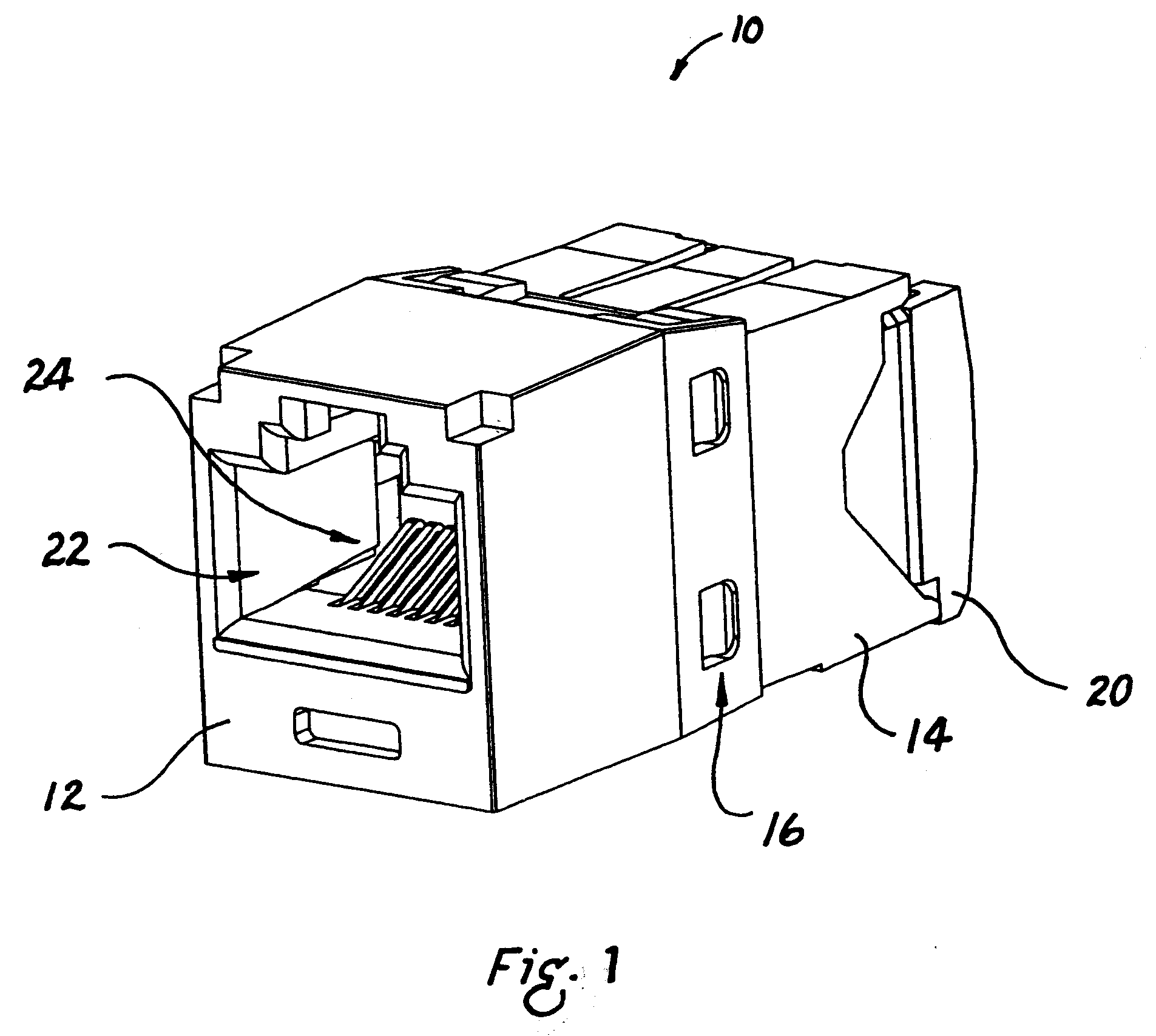
[0005]FIG. 1 is a front perspective view of a communications jack;

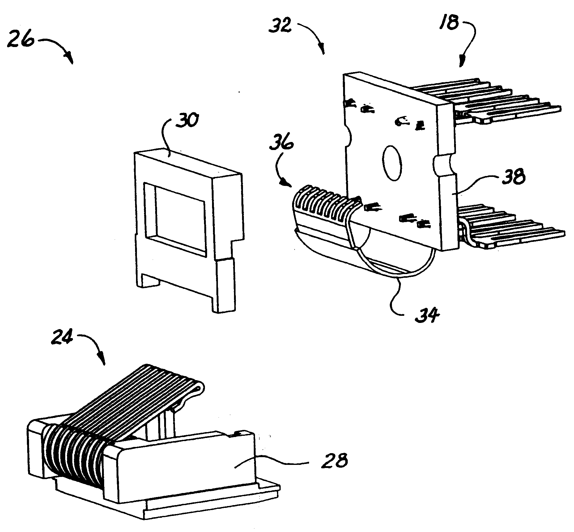
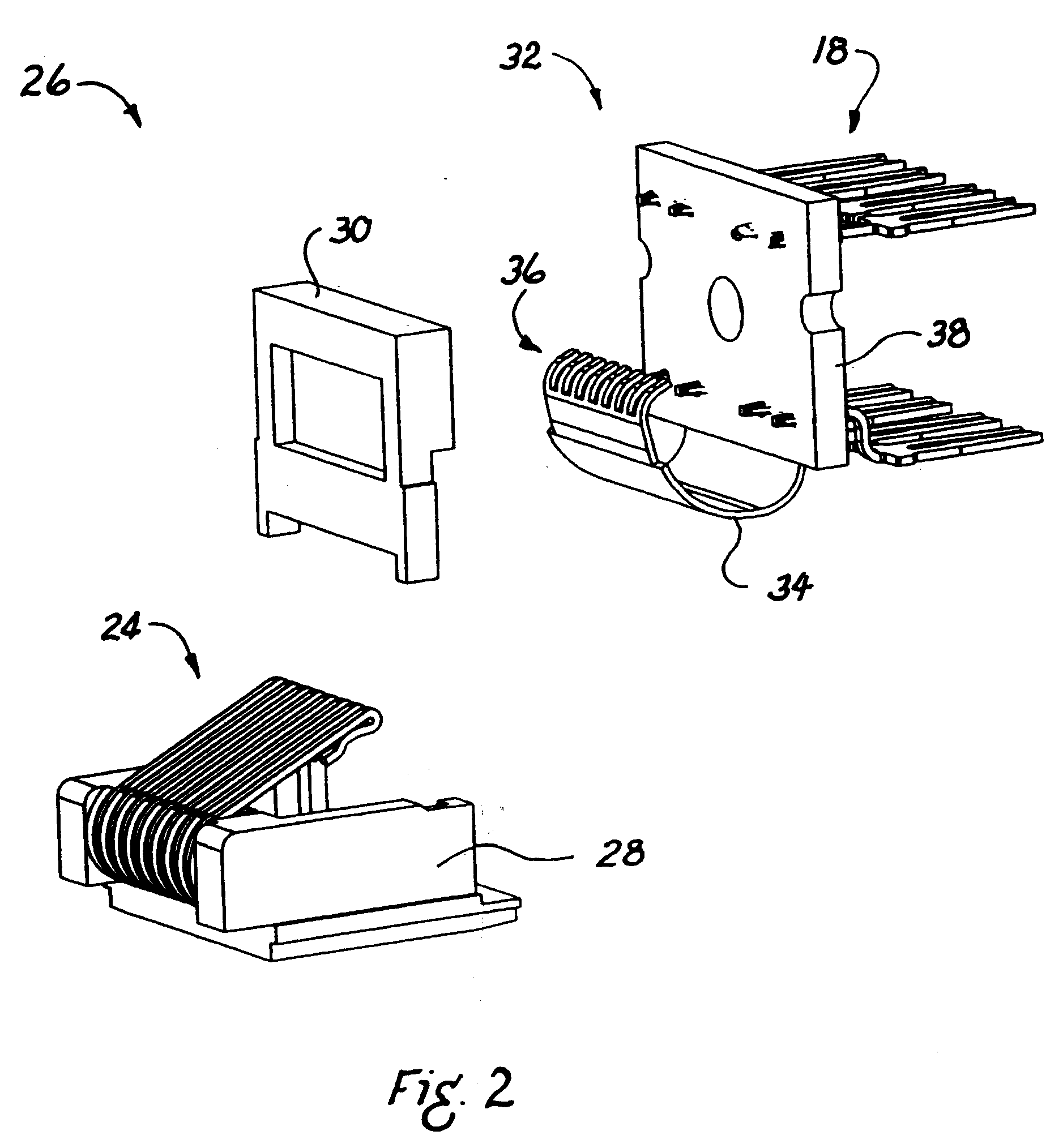
[0006]FIG. 2 is an exploded perspective view of a contact assembly showing the use of a printed circuit board having a flexible portion;

[0007]FIG. 3 is a plan view of a flexible portion of a printed circuit board;

[0008]FIG. 4 is a perspective view of an upper conductive trace of the flexible portion of FIG. 3;

[0009]FIG. 5 is a perspective view of a lower conductive trace of the flexible portion of FIG. 3;

[0010]FIG. 6 is a cross-sectional view along the line 6-6 of FIG. 3;

[0011]FIG. 7 is a cross-sectional view along the line 7-7 of FIG. 3;

[0012]FIG. 8 is a plan view of a printed circuit board showing a flexible portion and a rigid portion;

[0013]FIG. 9 is a diagram showing a side view and a plan view of jack contact points of a flexible portion of a printed circuit, with first and eighth connection extensions shown in extended positions;

[0014]FIG. 10 is a diagram showing a side view and a plan view of jack cont...


PUM


Abstract

A communications connector with a flexible printed circuit board is provided. The flexible printed circuit board is electronically and mechanically connected to the plug interface contacts of the jack near the plug/jack interface, in order to provide effective crosstalk compensation. The flexible printed circuit board has fingers at one end allowing it to flex as individual plug interface contacts are depressed when a plug is installed into the jack. The flexible printed circuit board, or a flexible portion of a printed circuit board, is provided with elongated extensions for certain conductors to accommodate the connection of six-contact or eight-contact plugs to the connector.

Description

CROSS-REFERENCE TO RELATED APPLICATIONS [0001] This application claims the benefit of U.S. Provisional Patent Application No. 60 / 699,823 filed Jul. 15, 2005. This application incorporates by reference in their entireties U.S. patent application Ser. No. 11 / 014,097, filed Dec. 15, 2004; U.S. patent application Ser. No. 11 / 055,344, filed Feb. 20, 2005; U.S. patent application Ser. No. 11 / 078,816, filed Mar. 11, 2005; U.S. patent application Ser. No. 11 / 099,110, filed Apr. 5, 2005; U.S. Provisional Application No. 60 / 587,416, filed Jul. 13, 2004; U.S. Provisional Application No. 60 / 637,024, filed Dec. 17, 2004.FIELD OF THE INVENTION [0002] The present invention relates generally to electrical connectors, and more particularly, to a communication jack having crimped contacts secured to a flexible printed circuit. BACKGROUND OF THE INVENTION [0003] In the communications industry, as data transmission rates have steadily increased, crosstalk due to capacitive and inductive couplings among...

Claims


Application Information

Patent Timeline
IPC IPC(8): H01R24/00H01R13/6461H01R13/719
CPCH01R13/6658H05K1/0228H05K1/189H01R13/6466Y10S439/941H01R24/64H05K2201/10189
Inventor CAVENEY, JACK E.LESNIAK, SCOTT M.
Owner PANDUIT
Why Eureka
Try Eureka