
Method and Apparatus for Optimizing the Continuous Positive Airway Pressure for Treating Obstructive Sleep Apnea

a positive airway pressure and obstructive sleep apnea technology, applied in the field of positive airway pressure optimization, can solve the problems of obstructing the upper airway during sleep, excessive daytime somnolence, spectrum of respiratory disturbances, etc., and achieves controlled positive increased or decreased pressure to the patient, and periodic reduction of controlled positive pressure

Inactive Publication Date: 2007-01-18
NEW YORK UNIV
View PDF57 Cites 32 Cited by
  • Summary
  • Abstract
  • Description
  • Claims
  • Application Information

AI Technical Summary

Benefits of technology

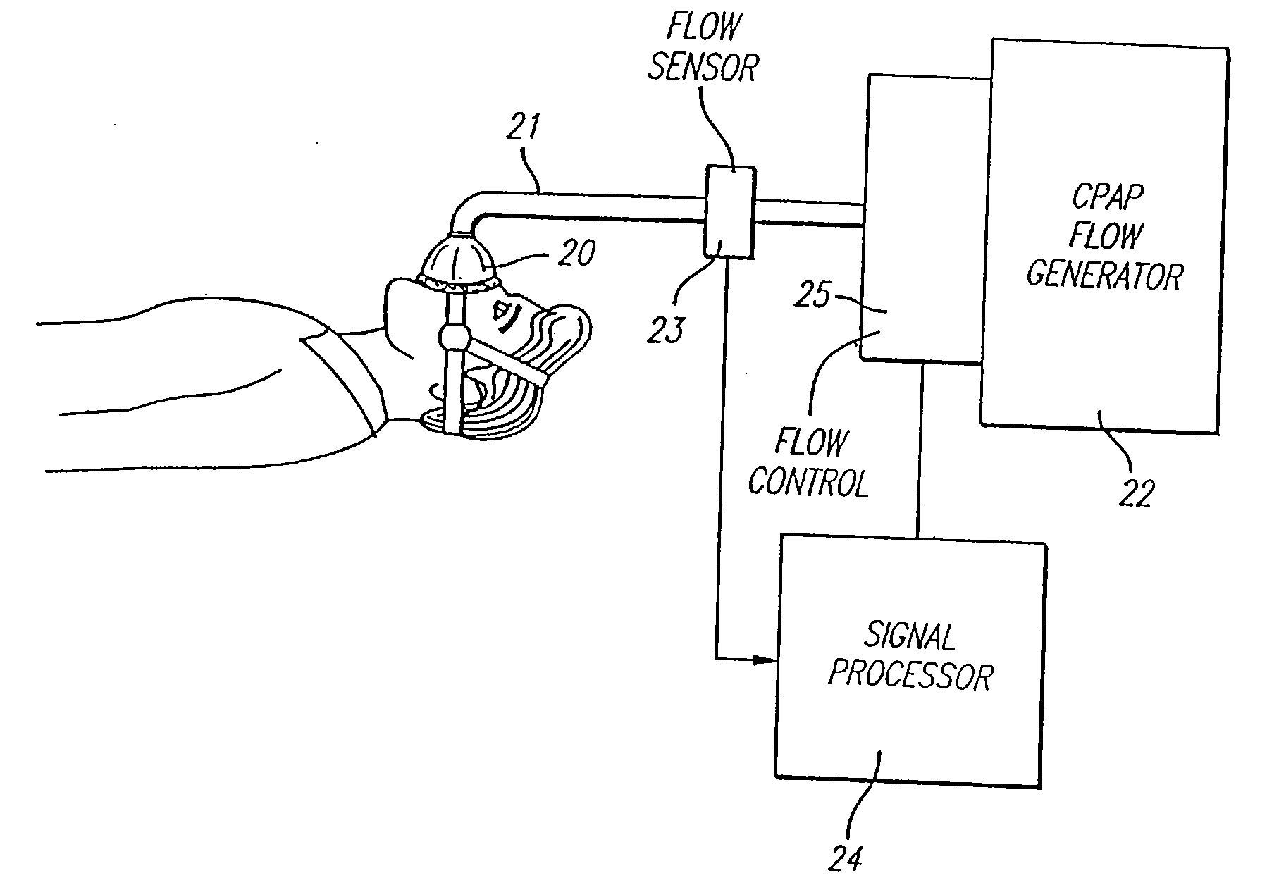
[0009] In accordance with the invention, an apparatus for the treatment of obstructive sleep apnea is provided, comprising a source of air, and means for directing an air flow from said source to a patient. This part of the system may be of the type disclosed, for example, in U.S. Pat. No. 5,065,756. In addition, means are provided for sensing the waveform of said airflow, to detect deviations therein that correspond to flow limitation in the air supplied to the patient. Such deviations may be, for example, deviations from a substantially sinusoidal waveform, flattening, or the presence of plateaus, in the portions of the waveform corresponding to inspiration of the patient. In response to such variations in said airflow, the system of the invention increases or decreases the pressure to the patient.

Problems solved by technology

OSAS is one of the most common causes of excessive daytime somnolence.
The obstruction results in a spectrum of respiratory disturbances ranging from the total absence of airflow (apnea) to significant obstruction with or without reduced airflow (hypopnea and snoring), despite continued respiratory efforts.
However, it is now well recognized that obstruction of the upper airway during sleep is in part due to the collapsible behavior of the supraglottic segment during the negative intraluminal pressure generated by inspiratory effort.
The availability of this non-invasive form of therapy has resulted in extensive publicity for apnea and the appearance of large numbers of patients who previously may have avoided the medical establishment because of the fear of tracheostomy.
Despite its success, limitations to the use of nasal CPAP exist.
These mostly take the form of discomfort from the mask and the nasal pressure required to obliterate the apneas.
Furthermore, the therapeutic pressure may both rise or fall with time in patients with changing anatomy (nasal congestion / polyps), change in weight, changing medication or with alcohol use.
Retesting is often necessary if the patient complains of incomplete resolution of daytime sleepiness, and may reveal a change in the required pressure.

Method used


Image

  • Method and Apparatus for Optimizing the Continuous Positive Airway Pressure for Treating Obstructive Sleep Apnea
  • Method and Apparatus for Optimizing the Continuous Positive Airway Pressure for Treating Obstructive Sleep Apnea
  • Method and Apparatus for Optimizing the Continuous Positive Airway Pressure for Treating Obstructive Sleep Apnea

Examples


Embodiment Construction

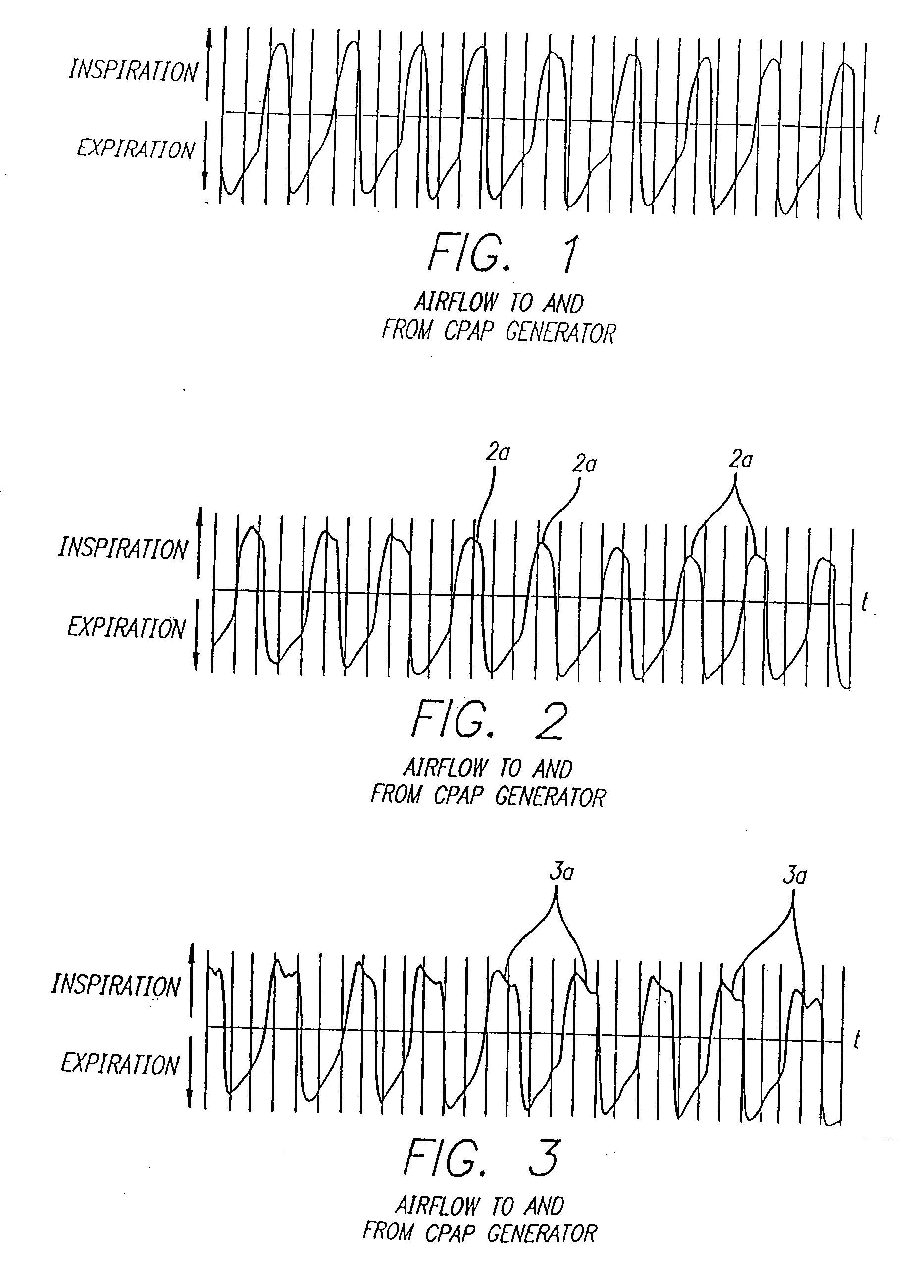
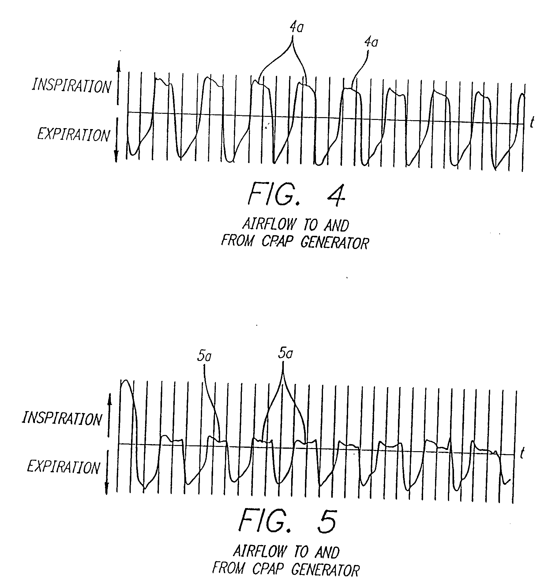
[0037]FIGS. 1-5 illustrate the waveforms of flow from a CPAP generator, obtained during the testing of a patient, in sleep studies. In these tests, the patient was wearing a CPAP mask connected to an air source, in the manner illustrated in U.S. Pat. No. 5,065,765. Each of these tests illustrate an epoch of 30 seconds, with the vertical lines depicting seconds during the tests. FIGS. 1-5 depict separate sweeps that were taken from 1 to 2 minutes apart, and with different pressures from the source of air.

[0038]FIG. 1 illustrates a “normal” waveform, in this instance with a CPAP pressure of 10 cm H2O. This pressure was identified as corresponding to apnea free respiration. It is noted that this waveform, at least in the inspiration periods, is substantially sinusoidal. The waveforms of FIGS. 2-5 illustrate that, as the controlled positive pressure is lowered, a predictable index of increasing collapsibility of the airway occurs, prior to the occurrence of frank apnea, periodic breath...


PUM


Abstract

A breathing apparatus is provided for the treatment of obstructive sleep apnea that optimizes the positive pressure to the airway of a patient. The apparatus is configured to detect flow limitations in the patient airway from an analysis of inspiratory flow waveforms. The airway pressure setting is raised, lowered or maintained depending on whether a flow limitation has been detected and on the previous actions taken by the apparatus. The apparatus may include a blower, a flow sensor, a pressure sensor, a microprocessor, a pressure controller and a nasal fitting. The apparatus is configured to increase the airway pressure when a flow limitation is detected in the airway of the patient and to decrease the airway pressure when a flow limitation is not detected.

Description

CROSS-REFERENCES TO RELATED APPLICATIONS [0001] This application is a continuation of U.S. Ser. No. 10 / 290,936, filed Nov. 7, 2002, which is a continuation of U.S. Ser. No. 09 / 602,158, filed Jun. 22, 2000 (U.S. Pat. No. 6,488,634), which is a continuation of U.S. application Ser. No. 08 / 644,371, filed May 10, 1996 (U.S. Pat. No. 6,299,581), which is a continuation of U.S. application Ser. No. 08 / 482,866, filed Jun. 7, 1995 (U.S. Pat. No. 5,535,739), which is a division of U.S. application Ser. No. 08 / 246,964, filed May 20, 1994 (U.S. Pat. No. 5,490,502), which is a continuation-in-part of U.S. application Ser. No. 07 / 879,578, filed May 7, 1992 (U.S. Pat. No. 5,335,654), the contents of which are hereby incorporated herein by reference.BACKGROUND OF THE INVENTION [0002] This invention relates to a method and apparatus for adjusting the positive airway pressure of a patient to an optimum value in the treatment of obstructive sleep apnea, and more particularly to a breathing device whi...

Claims


Application Information

Patent Timeline
Patent Type & Authority Applications(United States)
IPC IPC(8): A61B5/08A61M16/00A61B5/00A61B5/085A61B5/087A61B5/097A61B5/145A61B5/1455A61M16/06A61M39/22G06F17/00
CPCA61B5/0002A61M16/0677A61B5/6803A61M16/0051A61M39/228A61M2016/0036A61M2016/0039A61M2230/04A61M2230/08A61M2230/205A61M2230/62A61B5/4818A61M16/0069A61B5/7239A61M2230/005A61M16/026G16H50/30G16H20/40G16H50/20G16H40/63
Inventor RAPOPORT, DAVID M.NORMAN, ROBERT G.GRUENKE, ROGER A.
Owner NEW YORK UNIV
Learn More