Semi-active RFID tag and related processes

a technology of semi-active rfid tags and tags, which is applied in the direction of burglar alarms, mechanical actuation of burglar alarms, and the removal of hand-held items, etc., can solve the problems of slow data transmission speed, battery power drain, and significant limitation of the utility of active rfid tags, so as to prolong battery service life, save battery power, and optimize data transaction quality

Active Publication Date: 2007-01-25
PRECISION DYNAMICS CORPORATION
View PDF22 Cites 147 Cited by
  • Summary
  • Abstract
  • Description
  • Claims
  • Application Information

AI Technical Summary

Benefits of technology

[0006] In accordance with the invention, a semi-active radio frequency identification (RFID) tag and related reader system and process are provided, wherein the RFID tag includes an on-board flexible battery in combination with a power management system for optimizing data transaction quality by controllably enabling limited portions of the tag circuitry in a manner designed to conserve battery power and thereby prolong battery service life while maximizing the probability of a successful and complete data transaction. The on-board battery for powering the tag circuitry provides enhanced signal transmission range and variably rapid signal transmission speed suitable for use in a broad range of communication protocols, which in some embodiments may include tag-initiated communication.
[0007] The semi-active RFID tag is adapted for physical attachment onto a person or object associated therewith, as by incorporating the RFID tag into a lightweight flexible wristband or the like, wherein the wristband may be disposable. The RFID tag includes tag circuitry comprising, in accordance with one preferred form, a passive receiver including a suitable antenna and wake-up circuitry for signaling a control processor in the event that a communication session has been requested or initiated by a nearby reader. In one form, the receiver connects the processor or a circuit associated with the processor to the on-board battery. The processor then enables selected communication circuit blocks by appropriately coupling such circuit blocks to the on-board battery at times, durations and sequences sufficient to accommodate a successful communication transaction with the reader. Such communication circuit blocks may include analog-to-digital converters (ADC), and / or control and communications input-output (I / O) circuitry. By selectively enabling or powering limited portions of the tag circuitry on an as-needed basis only, battery power drain is substantially minimized while achieving the benefits of an optimized combination of enhanced communication range and improved data transfer speed.
[0009] For optimizing the benefits of small size and minimum cost, the semi-active tag may incorporate a single antenna structure designed for dual mode operation with respect to frequency and / or type. More particularly, the antenna structure may be adapted for relatively low power and short-range magnetic field (H-field) signal reception and / or transmission, or alternately for comparatively higher power and longer-range electric field (E-field) reception and / or transmission. In one preferred form, a single antenna structure is designed for respective low and high power operation at different frequencies which preferably conform with standard communication frequencies such as 13.56 megahertz (MHz) and 915 MHz compatible with existing reader technology.

Problems solved by technology

That is, the RFID tag has not been provided with an on-board battery for powering the RFID circuitry.
In such so-called “passive” RFID tags, communication is inherently and necessarily initiated only by the reader, and such communication has been limited to relatively short-range signal transmission and relatively slow data transmission speeds.
However, battery power drain has imposed a significant limitation on the utility of such active RFID tags.
That is, in a compact flexible RFID tag of the type used on a patient wristband on the like, size and other physical restraints on battery design, including but not limited to flexibility requirements in a compact and lightweight wristband design, inherently results in an on-board battery having limited charge storage capacity.

Method used


Image

  • Semi-active RFID tag and related processes
  • Semi-active RFID tag and related processes
  • Semi-active RFID tag and related processes

Examples


Embodiment Construction

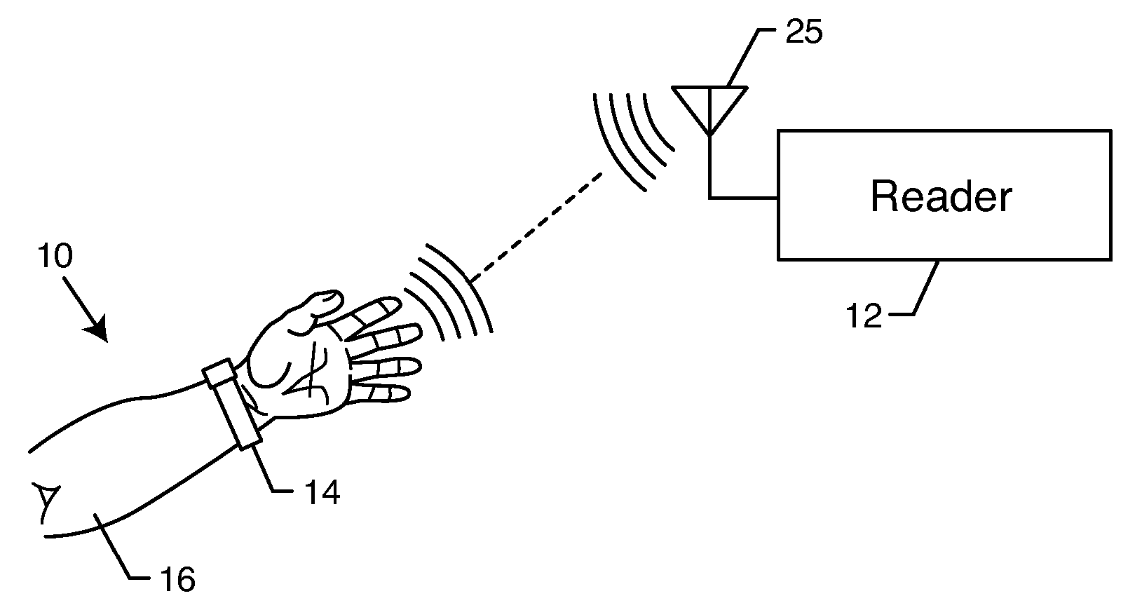
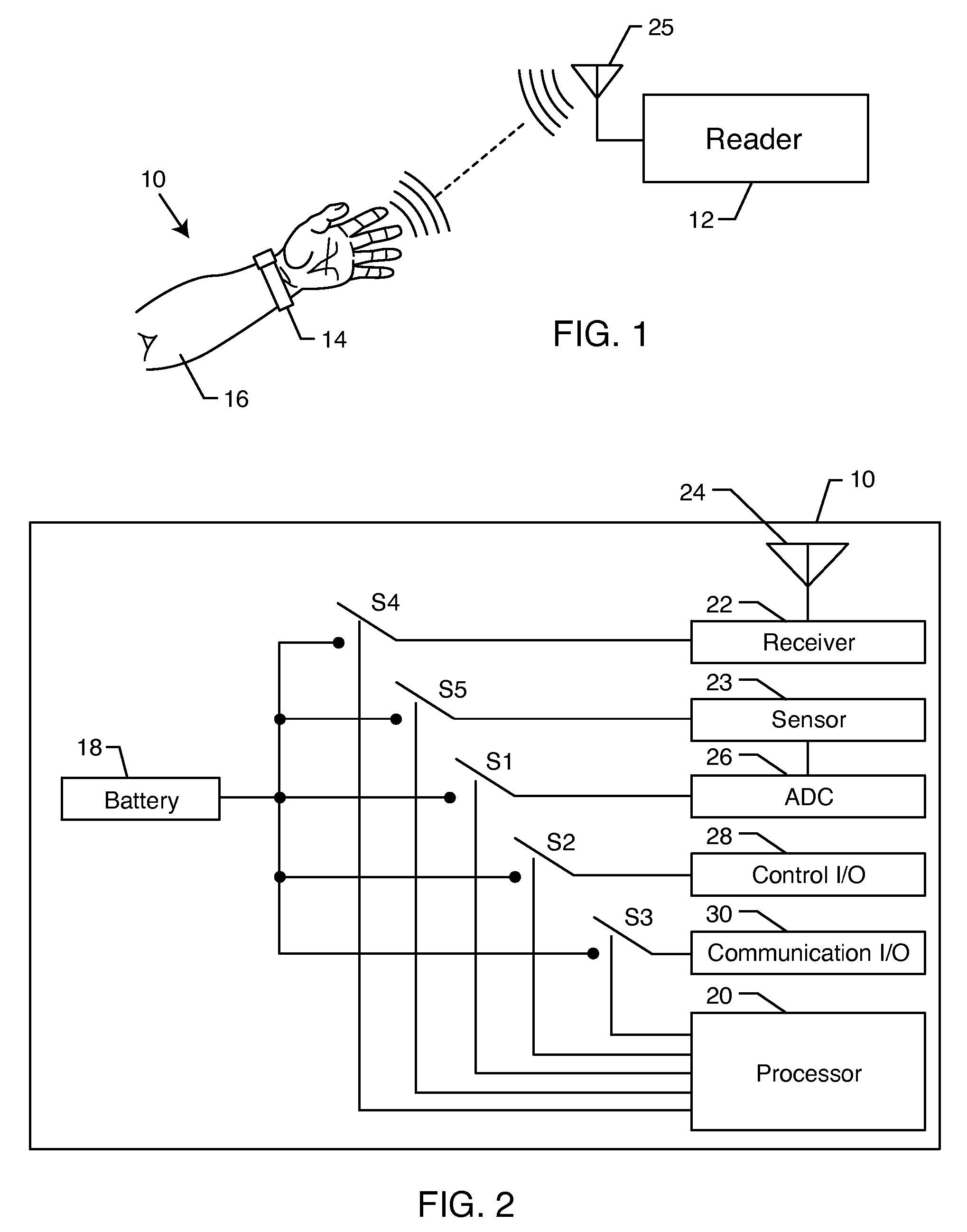
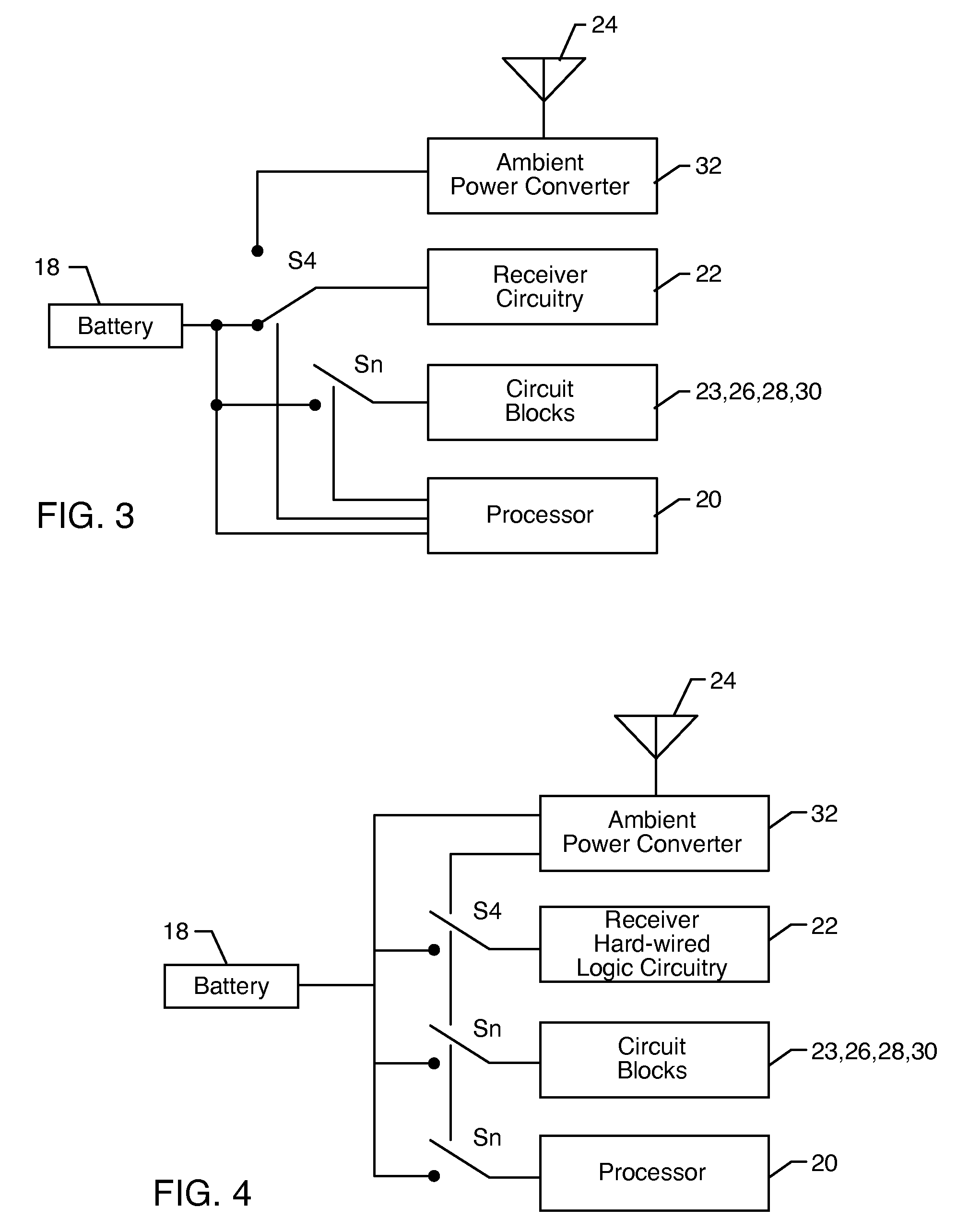
[0033] As shown in the exemplary drawings, an improved radio frequency identification (RFID) device or tag referred to generally in FIG. 1 by the reference numeral 10 is provided for communication with an associated reader 12. FIG. 1 shows the RFID tag 10 mounted onto or otherwise incorporated within a structure such as the illustrative flexible wristband 14 for mounting or attaching the tag 10 onto a person 16 or object associated therewith. In accordance with a primary aspect of the invention, the tag 10 includes an on-board flexible battery 18 (FIGS. 2-4) in combination with a power management system for controllably enabling limited portions of the tag circuitry in a manner designed to conserve battery power and thereby prolong battery service life. The inclusion of the on-board flexible battery 18 beneficially enhances signal transmission range and accommodates relatively rapid and optimized signal transmission speeds suitable for use in a broad range of communication protocols...


PUM


Abstract

An improved radio frequency identification (RFID) tag and related reader system and process are provided, wherein the RFID tag includes an on-board battery for enhanced signal transmission range, relatively rapid signal transmission speed, and optimized completion of a data transaction between the tag and a reader. The RFID tag further includes a power management system for activating the tag battery on an as-needed basis, and for thereupon enabling limited portions of the tag circuitry as required for a specific communication protocol, thereby conserving battery power and prolonging battery service life. In one preferred form, the battery is integrated with an antenna structure of single or dual mode with respect to frequency or type. This combination battery-antenna may be designed for recharging from a source of ambient energy.

Description

BACKGROUND OF THE INVENTION [0001] This invention relates generally to improvements in radio frequency identification (RFID) devices or tags, and related reader systems and processes for communicating therewith. More particularly, this invention relates to an improved, semi-active RFID tag adapted for association with a specific individual or object, as by mounting onto or within a wristband or the like, wherein the RFID tag incorporates an on-board thin, flexible, printable battery compatible with enhanced signal transmission range and relatively rapid signal transmission speed, and further wherein the tag includes a power management system for conserving battery power and thereby prolonging battery service life. The power management system is designed for activating the tag battery on an as-needed basis, and for minimizing battery power drain by enabling limited portions of the tag circuitry as required for a specific communication protocol and its operation predetermined by “supe...

Claims


Application Information

Patent Timeline
Patent Type & Authority Applications(United States)
IPC IPC(8): G08B13/14
CPCG06K19/07345G08B21/245G06K19/07762G06K19/0739H01Q1/2225H01Q1/44
Inventor BEIGEL, MICHAEL L.TUTTLE, JOHN R.
Owner PRECISION DYNAMICS CORPORATION
Why Eureka
Try Eureka