Continuous passive and active motion machine for the ankle

a passive and active motion technology, applied in the field of ankle passive and active motion machines, can solve the problems of dangerous use of machines and machine dangers

Inactive Publication Date: 2007-02-01
COST JAY ALAN
View PDF5 Cites 26 Cited by
  • Summary
  • Abstract
  • Description
  • Claims
  • Application Information

AI Technical Summary

Benefits of technology

[0010] The input capability of the computing device allows for the input of pre-defined parameters, which directs the machine how to move. Alternatively, the machine can be controlled manually. The machine ma

Problems solved by technology

In these cases and others, the machine can be dangerous because it may apply too much force to the lower extremities, for instance the ankle.
Moreover,

Method used


Image

  • Continuous passive and active motion machine for the ankle
  • Continuous passive and active motion machine for the ankle
  • Continuous passive and active motion machine for the ankle

Examples


Embodiment Construction

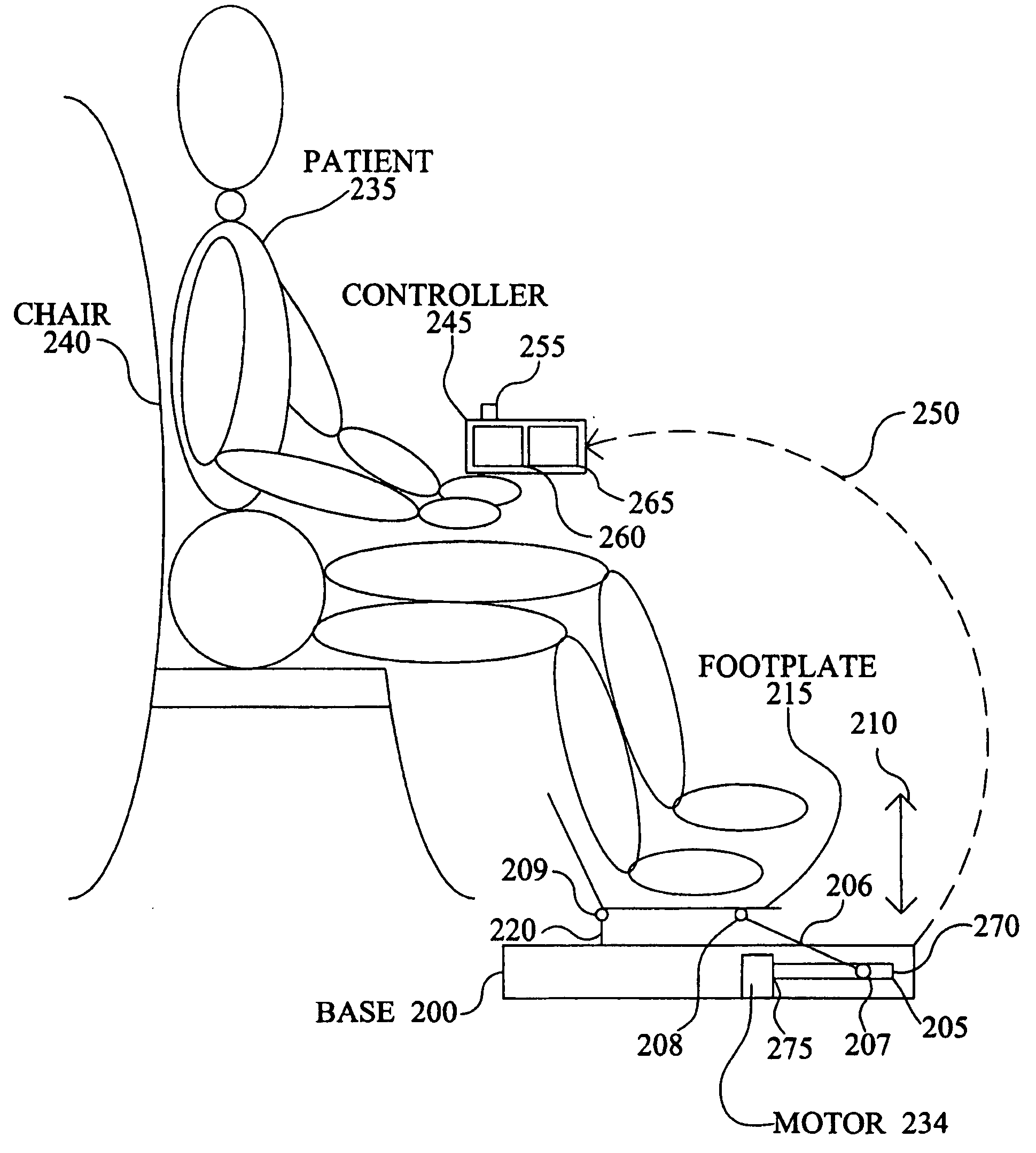
[0023] The present invention is a continuous passive and active motion machine for the ankle. The system is operated by causing the machine to be movable along a hinging mechanism connected to a foot plate. The patient's knee remains essentially stationary, while their ankle undergoes dorsi-flexion and plantar-flexion.

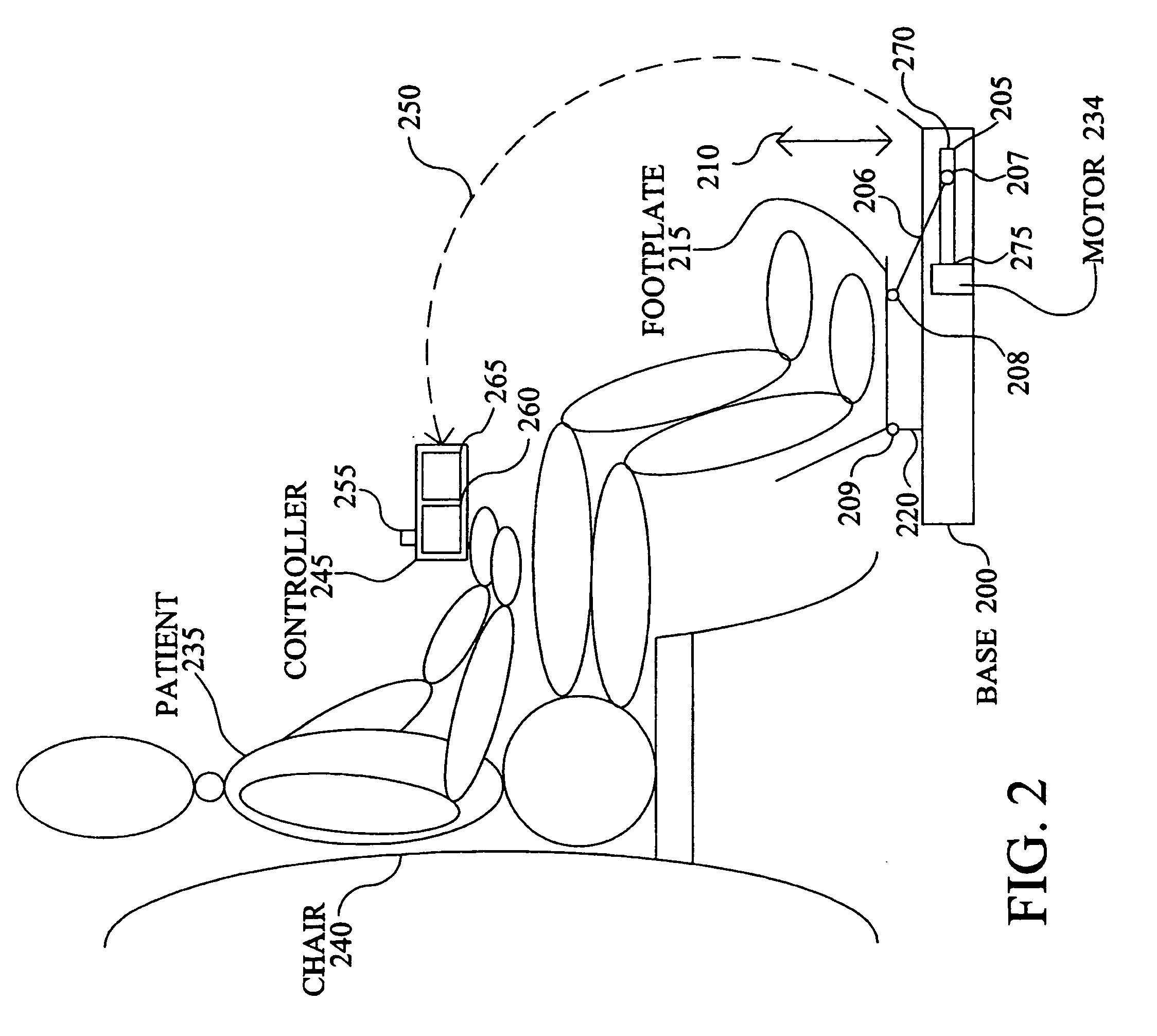
[0024] Continuous Passive and Active Motion Machine for the Ankle

[0025] An embodiment of the present invention is shown in connection with FIG. 2. Base 200 includes a glide track 205. Foot plate 215 is connected to support 220, which in turn is connected to base 200. Foot plate 215 is also connected to glide track 205 with a rod 206. Rod 206 has movable hinges 207 and 208 that allow rod 206 to move between a first end 275 and a second end 270 of glide track 205, for instance using a motor or hydraulic mechanism.

[0026] Foot plate 215 is thus moved in the directions of arrow 210 as hinging mechanism 209 connected to support 220 moves. Support 220 is affixed to base 20...


PUM


Abstract

The present invention is a continuous passive and active motion machine for the ankle. The invention includes a base configured to be placed on a flat, stable surface. The base is connected to a foot plate portion, which is connected to a drive shaft mechanism that moves along glide tracks using a motor. The foot plate is caused to move in a direction substantially perpendicular to movement of the drive shaft mechanism. Pressure sensors are added to provide feedback data to a controller. The controller potentially alters the behavior of the machine based on the provided feedback data.

Description

BACKGROUND OF THE INVENTION [0001] 1. Field of the Invention [0002] This invention relates generally to an apparatus for applying continuous passive and active motion to a human joint, and more particularly to a system that operates on the ankle. [0003] 2. Description of the Prior Art [0004]“Continuous Passive Motion” (CPM) is the concept of applying controlled, continuous movement to joints following joint injury or surgery. Machines have been developed to assist in the rehabilitative therapist's ability to apply CPM to patients. Different machines were designed for different joints. One machine was developed where a patient was able to perform dorsi-flexion and plantar-flexion on the ankle. [0005] The machine worked as shown in FIG. 1, the patient 100 lies in a bed 110. A brace 120 is used to make the knee 130 more or less stationary. Brace 120 might include straps above and / or below the knee to better secure the joint. Foot plate 140 has a hinging mechanism 150 that allows the fo...

Claims


Application Information

Patent Timeline
IPC IPC(8): A61H1/00
CPCA61H1/0266A63B23/085A61H2203/0431
Inventor COST, JAY ALAN
Owner COST JAY ALAN
Why Eureka
Try Eureka