
Electrosurgical device and methods

Active Publication Date: 2007-02-01
AVENT INC
View PDF105 Cites 107 Cited by
  • Summary
  • Abstract
  • Description
  • Claims
  • Application Information

AI Technical Summary

Problems solved by technology

Often, the tissue proximate to the probe heats up faster than tissue farther away from the probe, which may limit the size of the lesion.
In addition to limited lesion size, prior art devices typically form lesions with minimal extension distal to the tip of the electrode, as described by Bogduk et al.
Bogduk et al. suggest that failures of such prior art devices to effectively lesion target tissue was due to the fact that lesions created by those devices do not extend distal to the distal tip of the devices but rather extend primarily circumferentially to the distal tip, along the length of the exposed conductive portions.

Method used


Image

  • Electrosurgical device and methods
  • Electrosurgical device and methods
  • Electrosurgical device and methods

Examples


Embodiment Construction

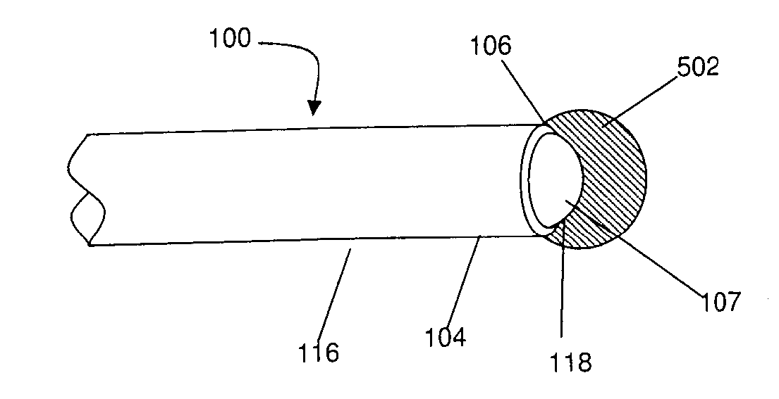
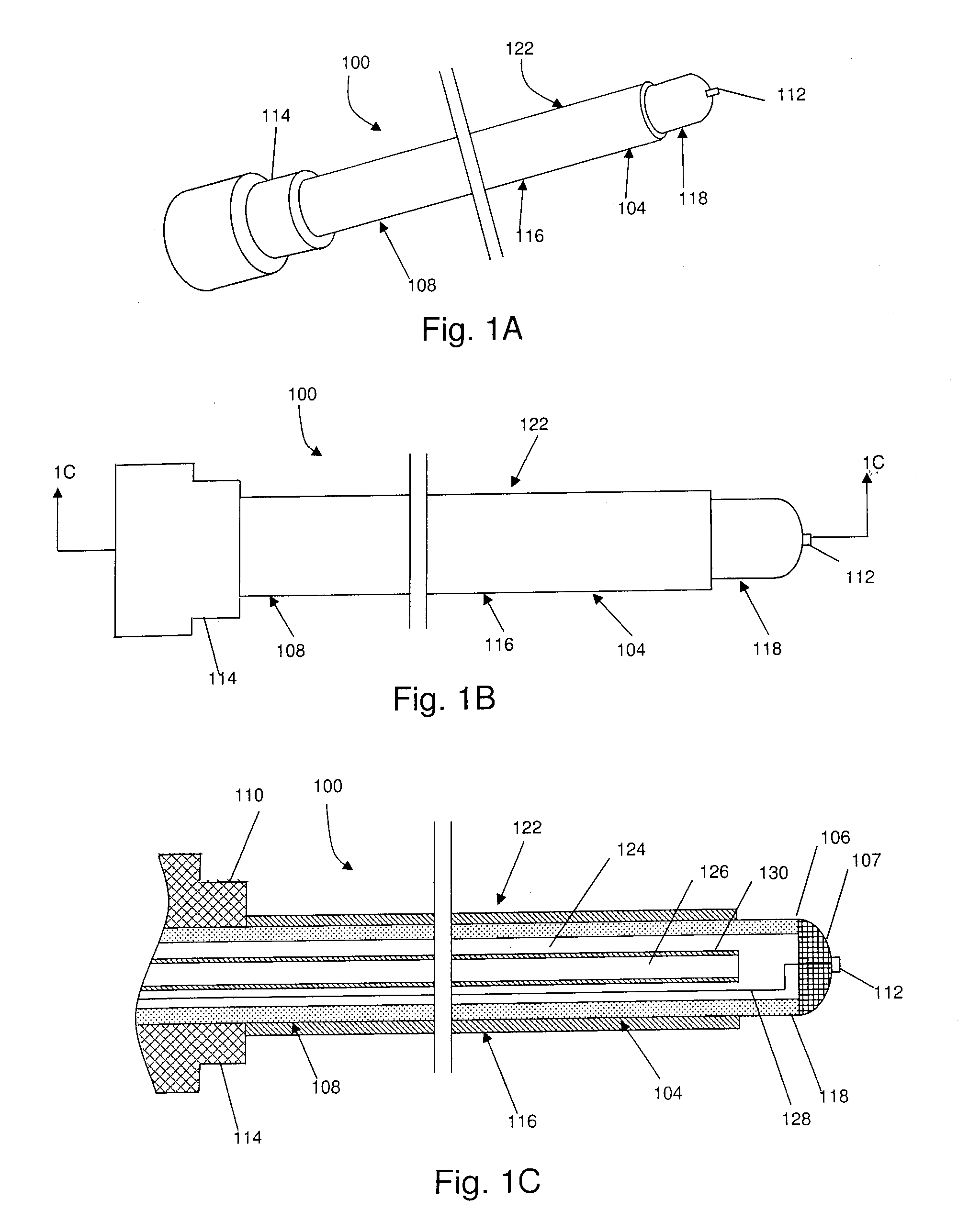
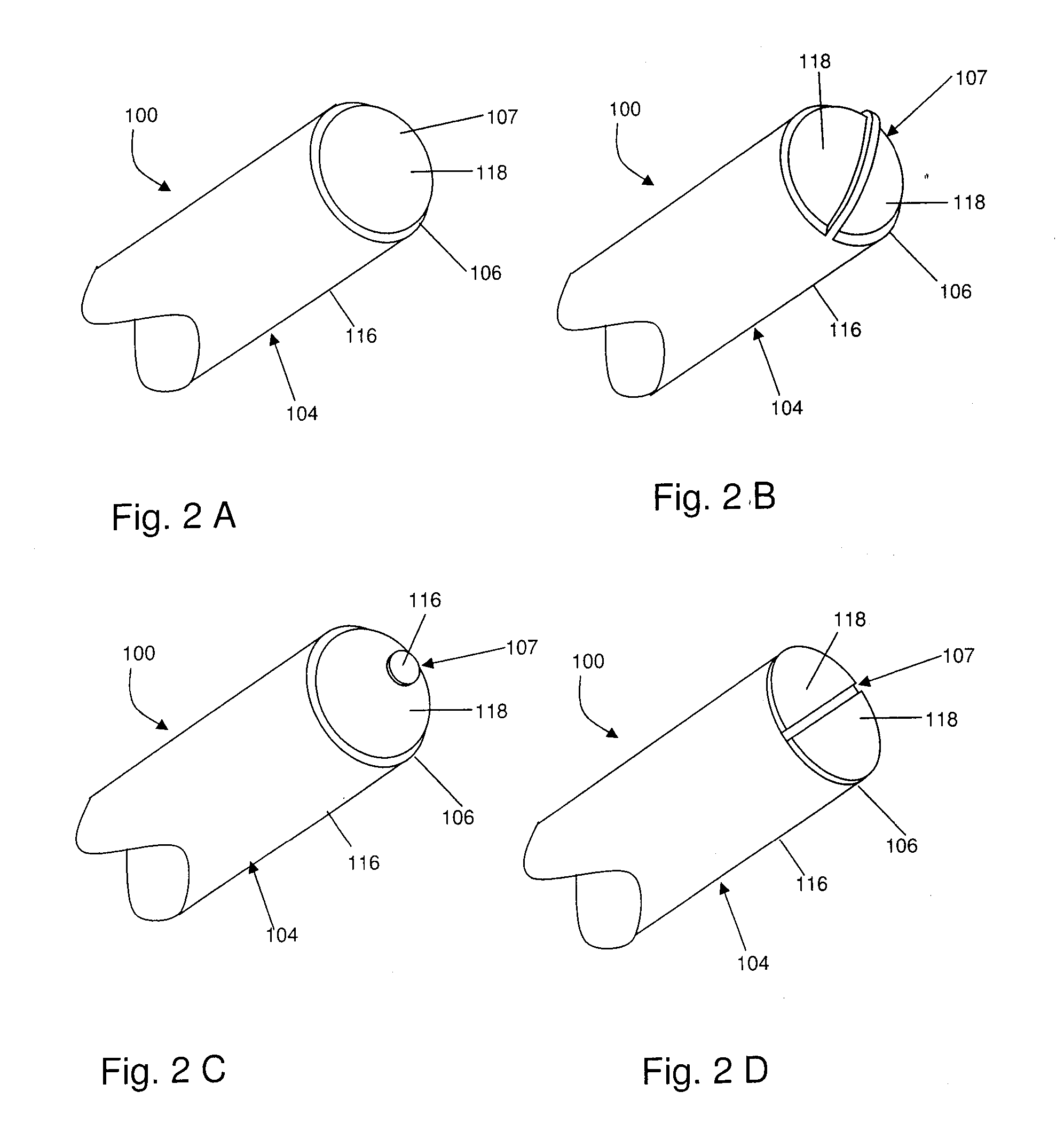
[0027] Embodiments of the invention described herein provide devices, systems, and methods which address some or all of the deficiencies of the current state of the art as described above. For example, in one broad aspect, embodiments of a device of the present invention may comprise an elongate member having one or more electrically insulated portions, and a distal face comprising one or more electrically exposed conductive portions for delivering energy substantially distal to the elongate member. At least one of the one or more electrically insulated portions may extend from a proximal region of the elongate member to the distal face.

[0028] In another broad aspect, a method is provided for creating a lesion at a target site within a body of a human or animal using an electrosurgical device. The method may comprise the steps of: inserting the electrosurgical device into the body such that the electrosurgical device is generally upstanding relative to the target site; and deliveri...


PUM


Abstract

A method and apparatus are disclosed for delivering energy substantially distal to an electrosurgical device. Embodiments of a device of the present invention may comprise an elongate member having one or more electrically insulated portions and a distal face comprising one or more electrically exposed conductive portions for delivering energy substantially distal to the elongate member. At least one of the one or more electrically insulated portions may extend from a proximal region of the elongate member to a distal end of the elongate member. In addition, a method is provided for creating a lesion at a target site within a body of a human or animal using an electrosurgical device. The method may comprise the steps of: inserting the electrosurgical device into the body such that the electrosurgical device is generally upstanding relative to the target site; and delivering energy from an energy source through a distal face of the electrosurgical device such that the energy is directed substantially distal to the distal face towards the target site.

Description

CROSS REFERENCES TO RELATED APPLICATIONS [0001] This application is a continuation-in-part of U.S. patent application Ser. No. 11 / 105,527 (filed on Apr. 14, 2005), Ser. No. 11 / 105,490 (filed on Apr. 14, 2005), and Ser. No. 11 / 105,524 (filed on Apr. 14, 2005), all of which claim the benefit of U.S. Provisional Patent Application 60 / 604,348 (filed on Aug. 25, 2004), and are continuations-in-part of U.S. patent application Ser. No. 10 / 087,856 (filed on Mar. 5, 2002), now U.S. Pat. No. 6,896,675. This application is also a continuation-in-part of U.S. patent application Ser. No. 11 / 381,783 (filed on May 5, 2006). This application is also a continuation-in-part of U.S. patent application Ser. No. 10 / 864,410 (filed on Jun. 10, 2004). This application is also a continuation-in-part of U.S. patent application Ser. No. 11 / 207,707 (filed on Aug. 22, 2005). U.S. patent application Ser. No. 11 / 207,707 is a continuation-in-part of U.S. patent application Ser. No. 11 / 079,318 (filed on Mar. 15, 20...

Claims


Application Information

Patent Timeline
IPC IPC(8): A61B18/14
CPCA61B18/1482A61B2018/00023A61B2018/00083A61B2018/00196A61B2018/00434A61B2218/007A61B2018/00791A61B2018/1497A61B2019/464A61B2218/002A61B2018/0044
Inventor GODARA, NEILHILLIER, TAYLOR
Owner AVENT INC
Learn More