Low profile prosthetic foot

a low-profile, prosthetic foot technology, applied in the field of low-profile prosthetic feet, can solve the problems of less efficient energy storage and release during motion of the foot, difficult to wholly contain in a cosmesis, bulky design of the foot, etc., and achieve the effect of increasing strength and resilien

Active Publication Date: 2007-02-01
OSSUR HF
View PDF22 Cites 89 Cited by
  • Summary
  • Abstract
  • Description
  • Claims
  • Application Information

AI Technical Summary

Benefits of technology

[0012] In at least one embodiment, a prosthetic foot is configured to provide a more fluid heel-to-toe movement during foot motion. Additionally, the prosthetic foot advantageously provides a low-profile foot for use by amputees with long residual limbs, as well as by amputees with shorter residual limbs. In at least some embodiments, the prosthetic foot further provides increased strength and resilience.
[0013] In one embodiment, an improved adapter is provided for attachment to a pylon or other leg prosthesis. The adapter is preferably mounted at a posterior section thereof to a posterior portion of a foot member, or other elongate support member, and includes an anterior portion configured to move relative to the foot member. In one preferred embodiment, the adapter is mounted in approximately the posterior 25% of the foot member, making the foot easier to remove from a cosmesis, facilitating access to the adapter and, for example, the bolts that connect it to the foot member. The foot member is preferably curved and optimized to flex.
[0016] In still another embodiment, the foot member and heel member can each be split into at least two independent members capable of flexing substantially independently of each other and substantially completely about their lengths during motion. This advantageously provides the prosthetic foot with increased stability.
[0017] In at least one embodiment, the prosthetic foot has improved strength and resiliency. For example, in one preferred embodiment, the prosthetic foot is rated for use in all impact levels. Additionally, the prosthetic foot can be used by amputees with weights varying over a wide range.

Problems solved by technology

However, such foot designs tend to be bulky and may be difficult to wholly contain in a cosmesis.
Additionally, in some instances the efficiency of the springs may deteriorate following prolonged use, resulting in less efficient energy storage and release during motion of the foot.
However, a split-toe foot alone may not provide the desired fluid range of motion of a human foot's natural stride.
However, many prosthetic foot designs are limited to a certain impact level and are designed for users in a certain weight range.
However, conventional foot designs are generally not designed to be used by both amputees with long residual limbs and those with shorter residual limbs, such as above-knee amputees.
However, many designs are difficult to maintain when enclosed in said cosmesis.
For example, the location of the ankle component or pyramid on some designs makes it difficult to remove the prosthetic foot from the cosmesis or to access the bolts connecting the ankle or pyramid to the prosthetic foot.

Method used


Image

  • Low profile prosthetic foot
  • Low profile prosthetic foot
  • Low profile prosthetic foot

Examples


Embodiment Construction

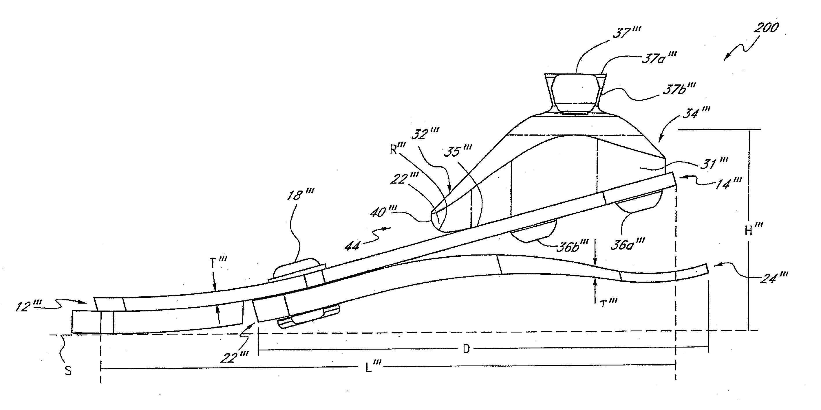
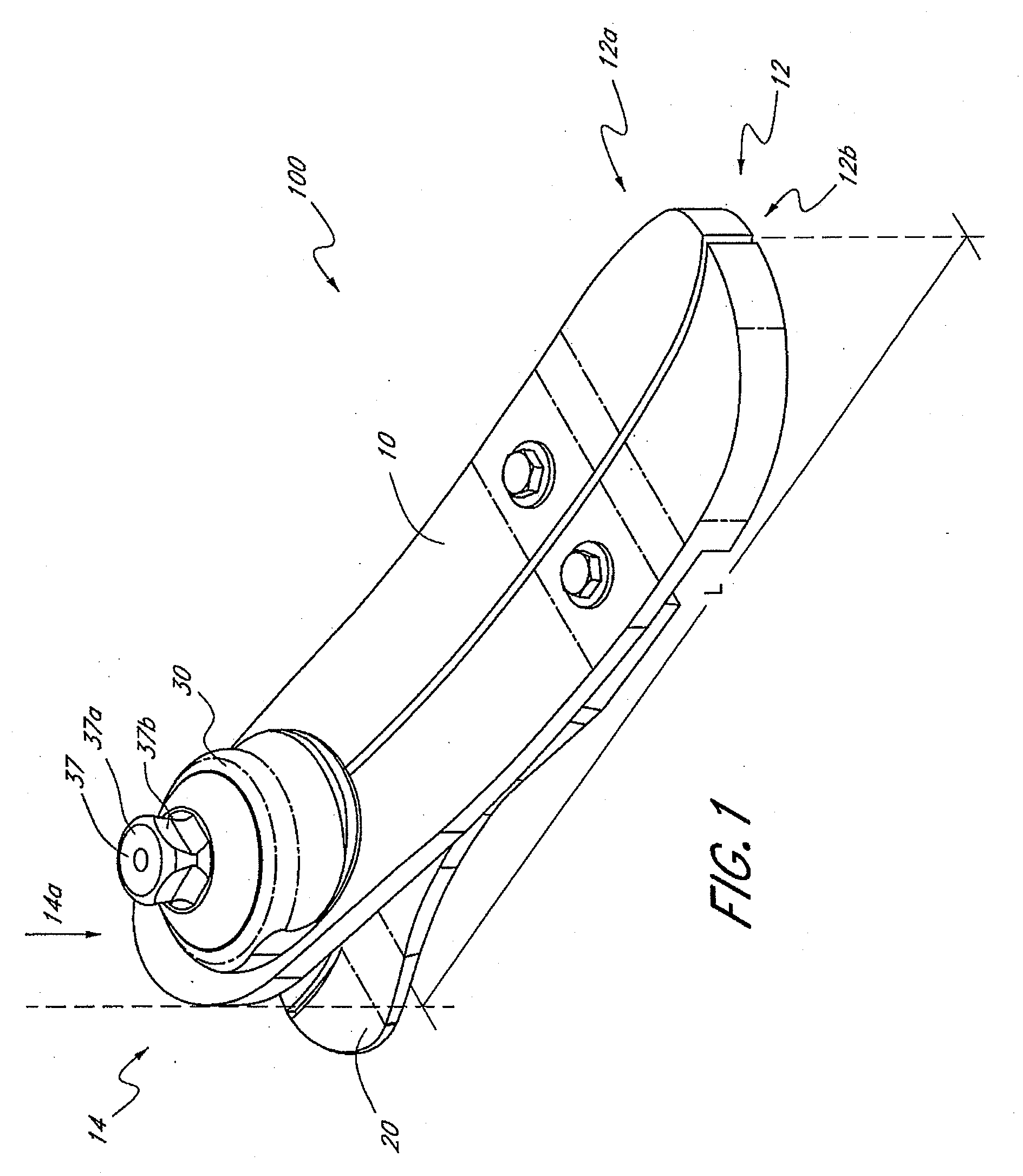
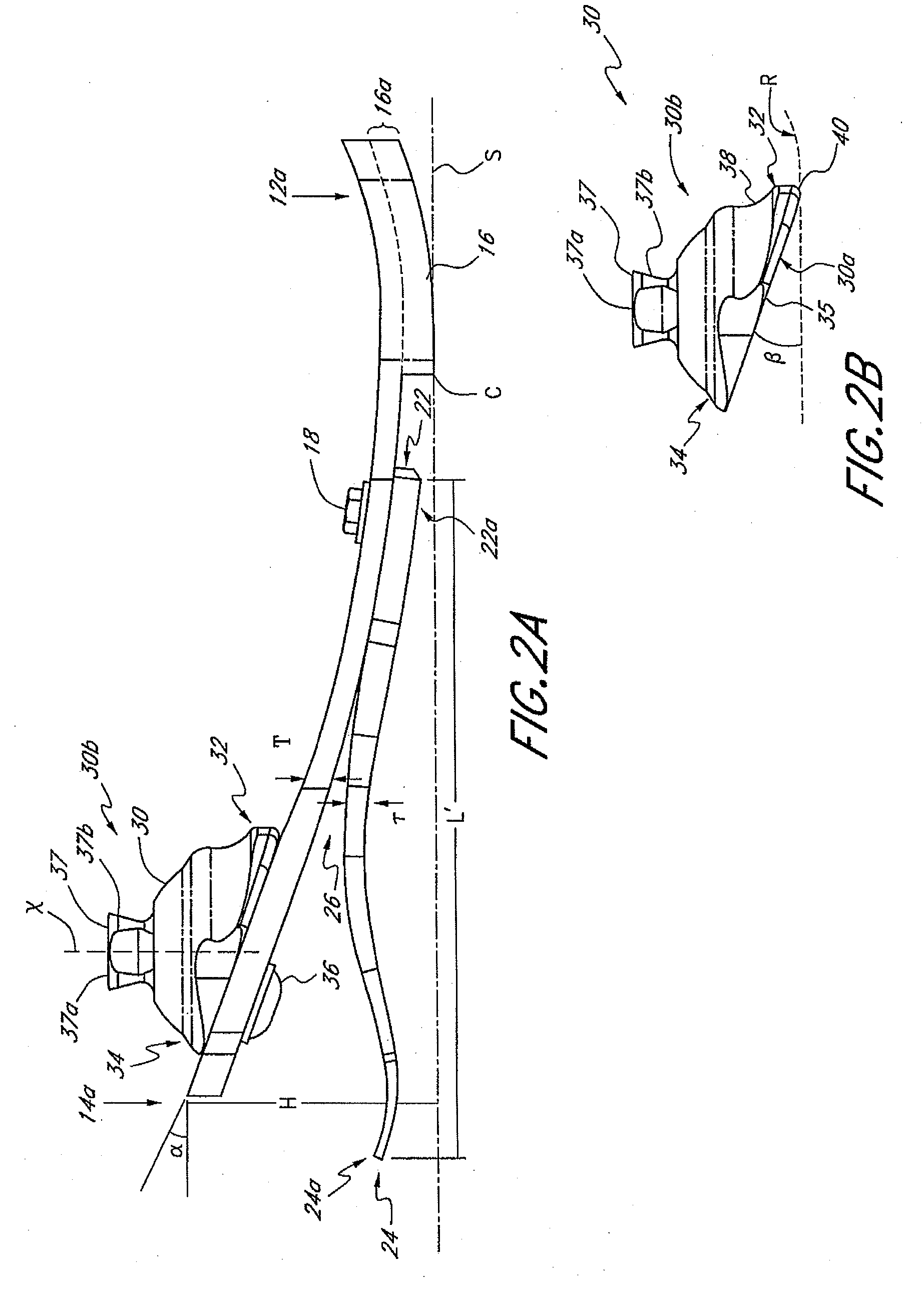
[0037]FIGS. 1-2A illustrate one embodiment of a prosthetic foot 100. Preferably, the prosthetic foot 100 comprises a foot member or support 10 which may have an elongate configuration having a length L extending between a front end 12 and a rear end 14. As used herein, length L refers to the horizontal length of the foot member 10 along a plane parallel to a support surface S on which the prosthetic foot 100 rests. In one embodiment, the length L may be between about 18 and 30 cm, corresponding to the specific size of the prosthetic foot 100. In one preferred embodiment, the length L is about 23 cm. The ends 12, 14 of the foot member 10 preferably have rounded or curved edges. The foot member 10 preferably also comprises an anterior portion 12a and a posterior portion 14a, wherein the anterior portion 12a can include a front toe portion 12b. In one preferred embodiment, the foot member 10 can be generally shaped like the sole of a human foot and the length L be approximately equal t...


PUM


Abstract

A low profile prosthetic foot comprises a foot member extending at an incline from an anterior portion to a posterior portion thereof and configured to flex during motion, and an adapter mounted solely at a posterior section thereof to the posterior portion of the foot member so that the adapter's anterior section can move relative to the foot member and “roll-up” onto the foot member during motion.

Description

CROSS-REFERENCE TO RELATED APPLICATIONS [0001] This application is a divisional application of U.S. application Ser. No. 10 / 642,125, filed Aug. 15, 2003, which is hereby incorporated by reference in its entirety and should be considered a part of this specification.BACKGROUND OF THE INVENTION [0002] 1. Field of the Invention [0003] Embodiments of the present invention relate to lower limb prostheses in general, and, in one embodiment, to a prosthetic foot having an adapter connected to a foot member, the adapter configured to provide improved foot member flexion. [0004] 2. Description of the Related Art [0005] Prosthetic feet of different designs are well known in the art. The various conventional designs have sought to solve various limitations associated with prosthetic feet. [0006] Some conventional designs attempt to provide the feel and fluid range of motion of a human foot's natural stride. One approach is to incorporate springs to store and release energy during motion of the...

Claims


Application Information

Patent Timeline
Patent Type & Authority Applications(United States)
IPC IPC(8): A61F2/66A61F2/00A61F2/50A61F2/76
CPCA61F2/66A61F2002/5083A61F2002/30434A61F2002/30438A61F2002/30448A61F2002/5003A61F2002/5007A61F2002/5055A61F2002/6621A61F2002/6642A61F2002/6664A61F2002/6685A61F2220/0041A61F2220/005A61F2/76A61F2002/30433A61F2/50A61F2/60A61F2002/5018A61F2002/5067A61F2002/5079A61F2002/6657
Inventor JONSSON, ORN INGVILECOMTE, CHRISTOPHE GUYCLAUSEN, ARINBJORN VIGGORAGNARSDOTTIR, HEIDRUN GIGJA
Owner OSSUR HF
Why Eureka
Try Eureka