Joining means

a technology of joining means and means, applied in the direction of manufacturing tools, forging/hammering/pressing machines, shaping tools, etc., can solve the problems of similar problems in pressing, embossing machines and punches, and achieve the effects of less expensive production of the complete c-bracket, simple and lasting, and economic benefits

Active Publication Date: 2007-02-15
NEWFREY
View PDF28 Cites 12 Cited by
  • Summary
  • Abstract
  • Description
  • Claims
  • Application Information

AI Technical Summary

Benefits of technology

[0006] Apart from those advantages of the invention which correspond to the objective of achieving an economical, simple and enduring coaxiality of ram tool and countertool, it is made possible in addition by the joining means according to the invention to realize with a C-bracket the various tool distances and the use of various tools in various materials as well as the use of tool holders with different diameter of the receiving bore. Besides, the tools, in case of wear or further development, can be more simply, more quickly and more economically retrofitted or adapted to new problems. This is especially advantageous because C-brackets are very costly. They are made in one piece with the holder as a rule, because of the exacting requirements on rigidity. By separate fabrication from two or more parts, the production of the complete C-bracket can be rendered less expensive, and the C-bracket production time is shortened.
[0007] The objects described in the dependent claims represent advantageous refinements of the subject of claim 1. It is advantageous in particular to make the interlayer wedge-shaped, since the axial position of the ram or countertool can be influenced in a particular direction. It is likewise of advantage to provide several contact surfaces at right angles to each other or formed by the inner surfaces of a U-shaped element, so that the tool is more stably configured in motion. A highly advantageous manifold serviceability of the holder with respect to the distance from the countertool is made possible if the holder and the corresponding end of the C-bracket are of such configuration that the holder is rotatable through 180°. Other advantages of the preferred embodiments will be found in the following description.

Problems solved by technology

Similar problems arise in pressing, embossing machines and punches, i.e. wherever two cooperating tools (ram and die or anvil) must be oriented coaxially with each other.

Method used


Image

  • Joining means
  • Joining means
  • Joining means

Examples


Embodiment Construction

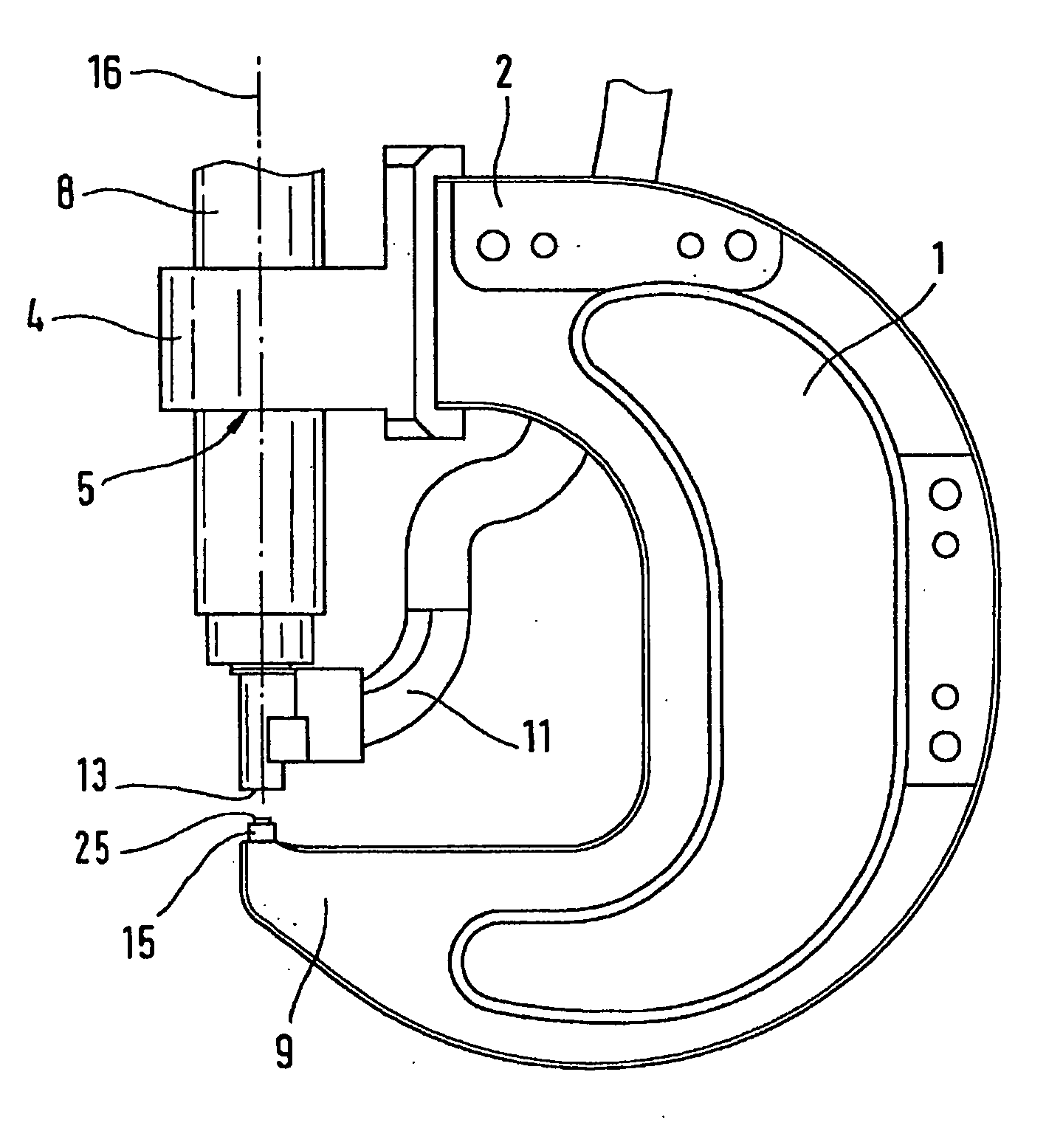
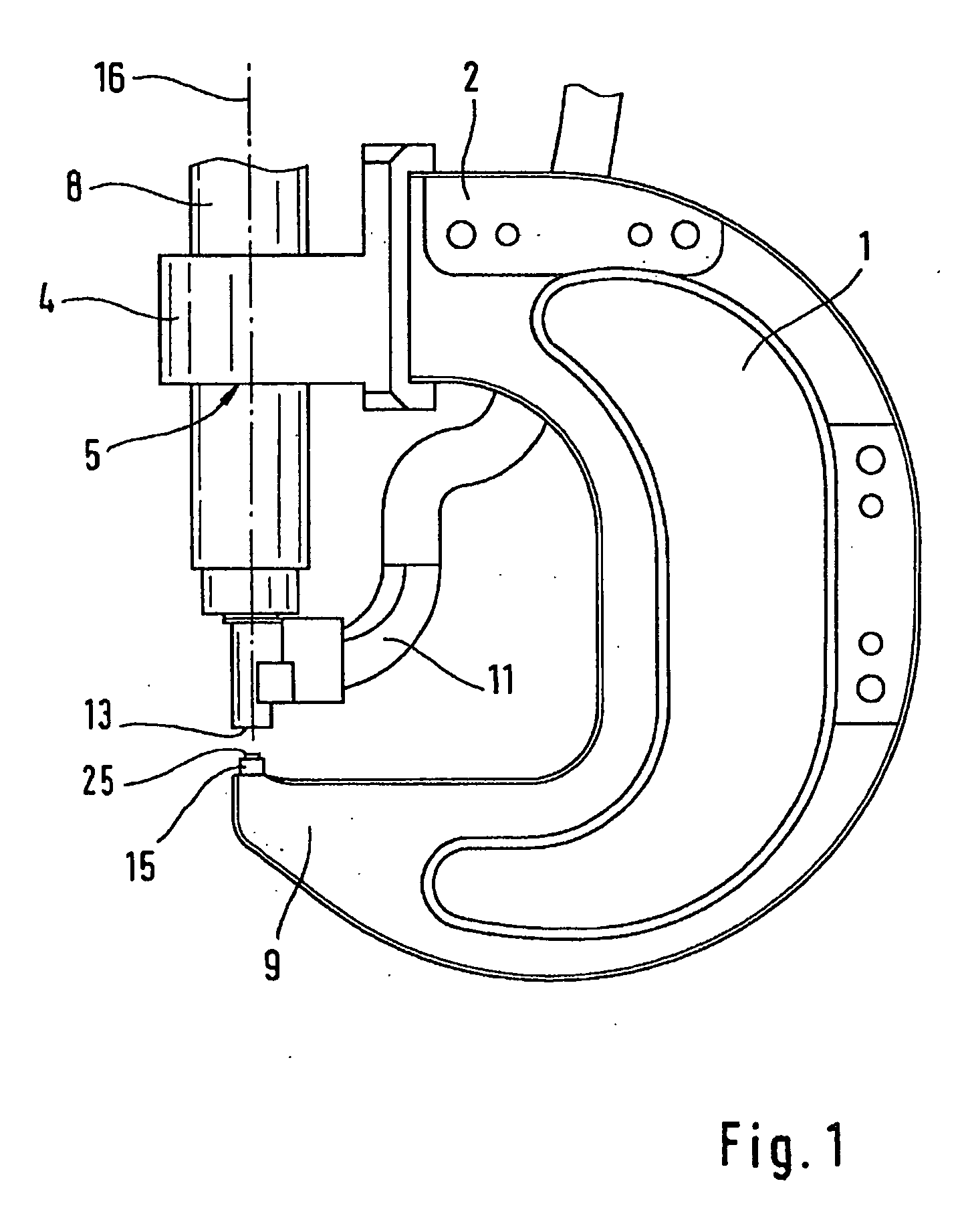
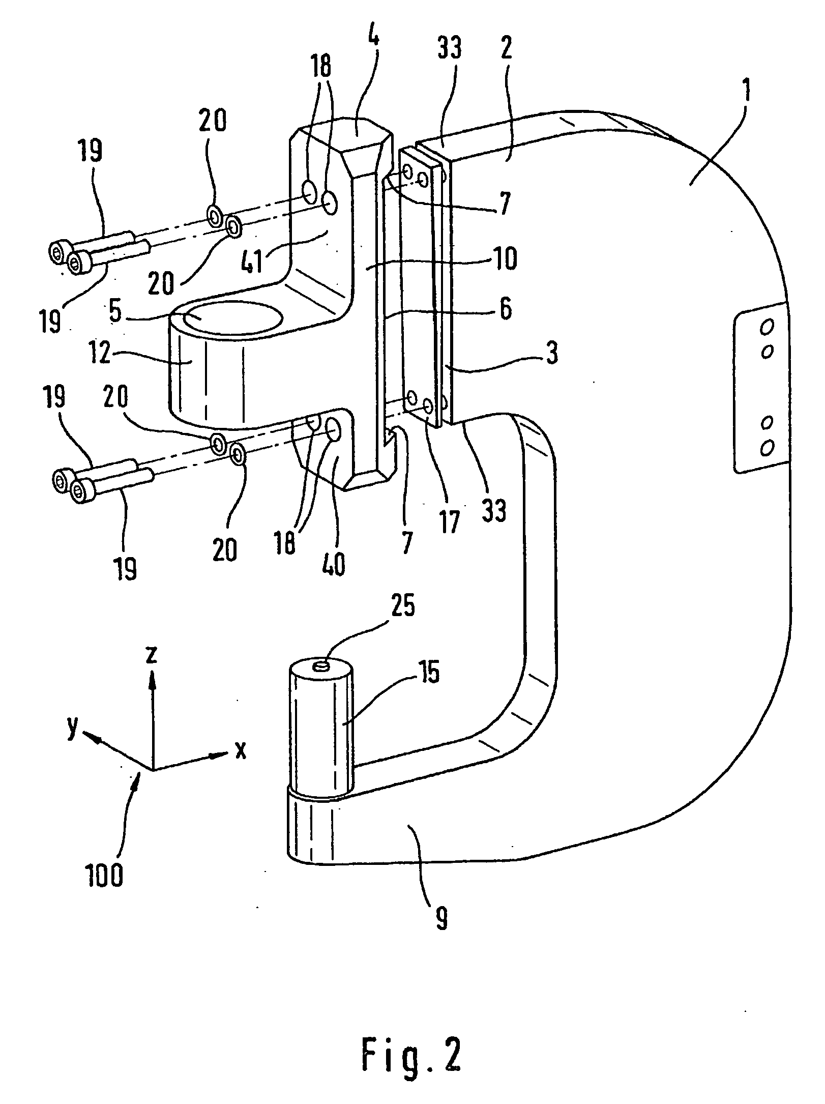
[0019]FIG. 1 shows parts of a joining means, in this case a self-piercing rivet means. On the C-bracket 1, at one end, in this case the upper end 2 of the C-bracket 1, a holder 4 is arranged in whose preferably cylindrical through opening or bore 5 a ram tool 8 is arranged, in this case a self-piercing rivet tool. Here FIG. 1 does not show that the ram tool 8 at its end away from the C-bracket 1 comprises a number of other means for moving the ram tool 8 and to supply energy. At the end of the ram tool 8 facing the other, in this case the lower end 9 of the C-bracket 1, there is a feed means 11 holding small parts, in this case self-piercing rivets, in readiness as required for the connection. The outermost end of the ram tool, facing the bottom end 9 of the C-bracket 1, comprises a ram 13. At the other bottom end 9 of the C-bracket 1, a die carrier 15 with a die or an anvil 25 is arranged. To produce a connection, for example, a self-piercing rivet arranged on the ram 13 is forced ...


PUM

PropertyMeasurementUnit
thicknessaaaaaaaaaa
contact surfacesaaaaaaaaaa
lengthaaaaaaaaaa

Abstract

In the invention, a joining means having a ram tool, a countertool and a holder with an opening to accommodate the ram tool or the countertool, is described. The two tools are arranged coaxial with each other at different ends of a C-bracket. The invention is distinguished in that the holder comprises at least one plane contact surface arranged on the outer surface of the holder, resting in contact with at least one plane face of the corresponding end of the C-bracket and detachably fastened thereto. Between the contact surface and the face, at least one interlay is arranged, determining the information and/or the distance of the contact surface from the face.

Description

CROSS REFERENCE TO RELATED APPLICATIONS [0001] This application is a continuation of PCT Patent Application Serial No. PCT / EP2005 / 001002, filed on Feb. 2, 2005, which claims priority to German Patent Application Serial No. DE 10 2004 005 884.9, filed on Feb. 5, 2004, both of which are incorporated by reference herein. BACKGROUND AND SUMMARY [0002] The invention relates to a joining means having a ram tool and a countertool, and a holder having an opening to accommodate the ram tool or the countertool. The two tools are oriented coaxial with each other at different ends of a C-bracket. [0003] Such joining means are known and serve in particular to produce connections, for example rivet and self-piercing rivet connections. Known joining means comprise a ram provided with a drive and, as countertool, a matching die, arranged coaxial with each other, exacting requirements being imposed on the coaxiality of ram and die, since the strength and appearance of the connection produced depend ...

Claims


Application Information

Patent Timeline
Patent Type & Authority Applications(United States)
IPC IPC(8): B21J15/10B21J13/03B21J15/02
CPCB21J13/03B21J15/025B21J15/10B21J15/105Y10T29/49943Y10T29/53065Y10T29/53991Y10T29/49897Y10T29/5377Y10T29/53704Y10T29/5343Y10T29/5397Y10T83/8746B21J15/30B21J15/36
Inventor OPPER, REINHOLDGUITERREZ ROMERO, RUBENHUFNER, GEORGWILL, LEONHARD
Owner NEWFREY
Why Eureka
Try Eureka