Alarm system with speaker

an alarm system and speaker technology, applied in fire alarms, electric controllers, instruments, etc., can solve the problems of not providing control signals to be issued by the system controller, prior art systems do not provide communication between the notification appliances and the system controller during supervisory mode, and not enough power to power the notification devices. , to achieve the effect of adequate headroom power

Inactive Publication Date: 2007-02-15
JOHNSON CONTROLS FIRE PROTECTION LP
View PDF12 Cites 34 Cited by
  • Summary
  • Abstract
  • Description
  • Claims
  • Application Information

AI Technical Summary

Benefits of technology

[0018] Moreover, using fire alarm system addressable notification appliance technology, such as SimplexGrinnell LP's TrueAlert® technology as described in U.S. Pat. No. 6,426,697, “Alarm System Having Improved Communication,” incorporated by reference herein in its entirety, any aspect of the speaker may be configured. For example, the tap of a speaker according an embodiment of the present invention can be set by addressing the speaker and commanding it, from a fire alarm control panel, to a particular tap setting, eliminating the need to remove the speaker from the ceiling or wall. If a speaker is deemed to be below an acceptable dB level, all that is needed is to select the “address” of that speaker, and set the new tap level, repeating the procedure until the desired level is achieved. Of course, an amplifier of adequate headroom power is necessary. Typically, many or most installations have more than enough amplifier power to accommodate changes of this type. Any other aspect of the speaker may be configured, such as the audio power of the speaker.

Problems solved by technology

Prior art systems have not provided for control signals to be issued from the system controller to the notification appliances during the term of the supervisory mode.
As such, prior art systems do not provide for communication between the notification appliances and the system controller during supervisory mode other than passive communication, such as monitoring the common power lines for a short circuit or other fault.
In a standby mode, only enough power is supplied to the plural notification appliances, at a first voltage level, to support two-way communications between a system controller and the notification appliances, but not enough power to power notification devices.

Method used


Image

  • Alarm system with speaker
  • Alarm system with speaker
  • Alarm system with speaker

Examples


Embodiment Construction

[0034] A description of preferred embodiments of the invention follows.

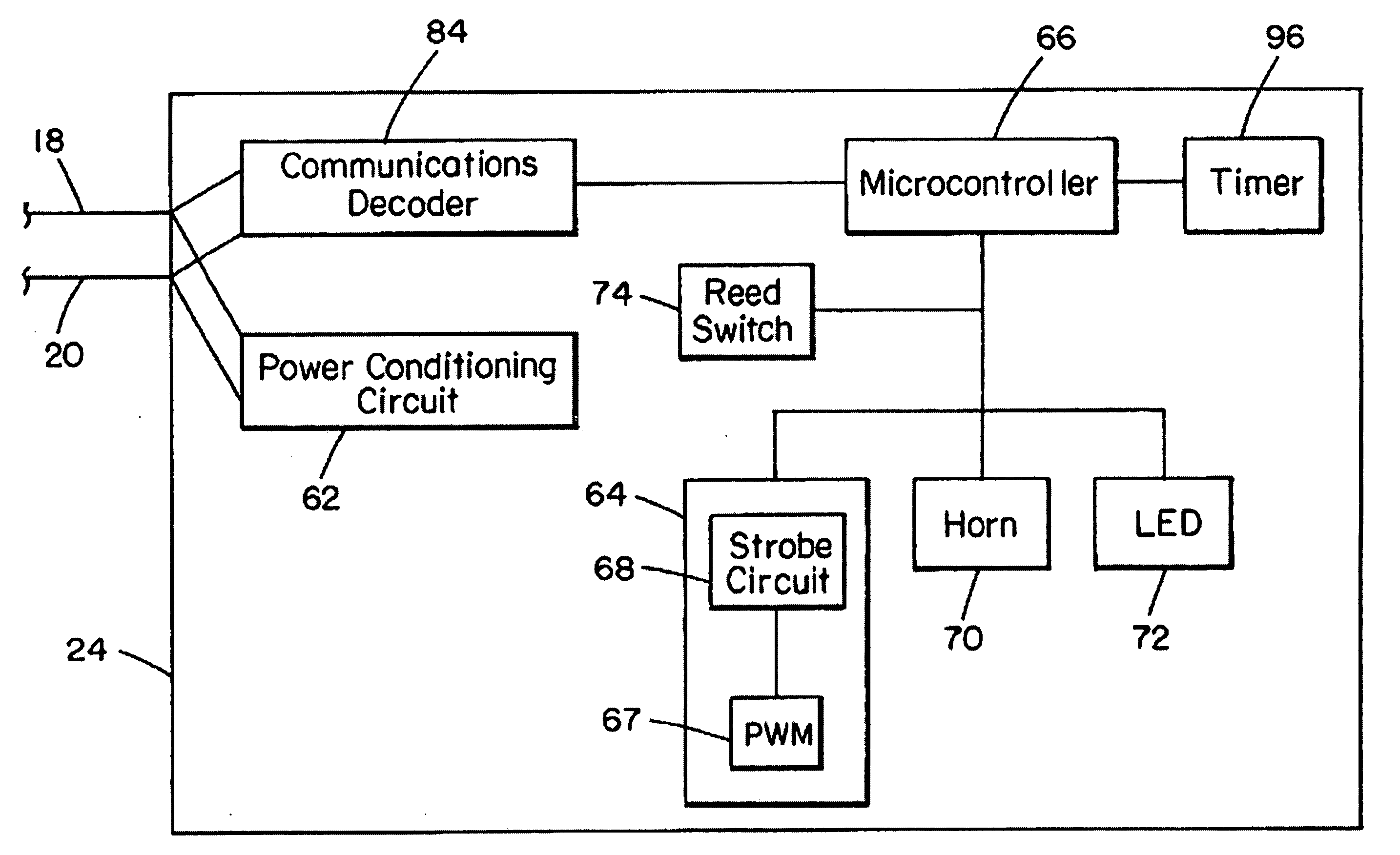
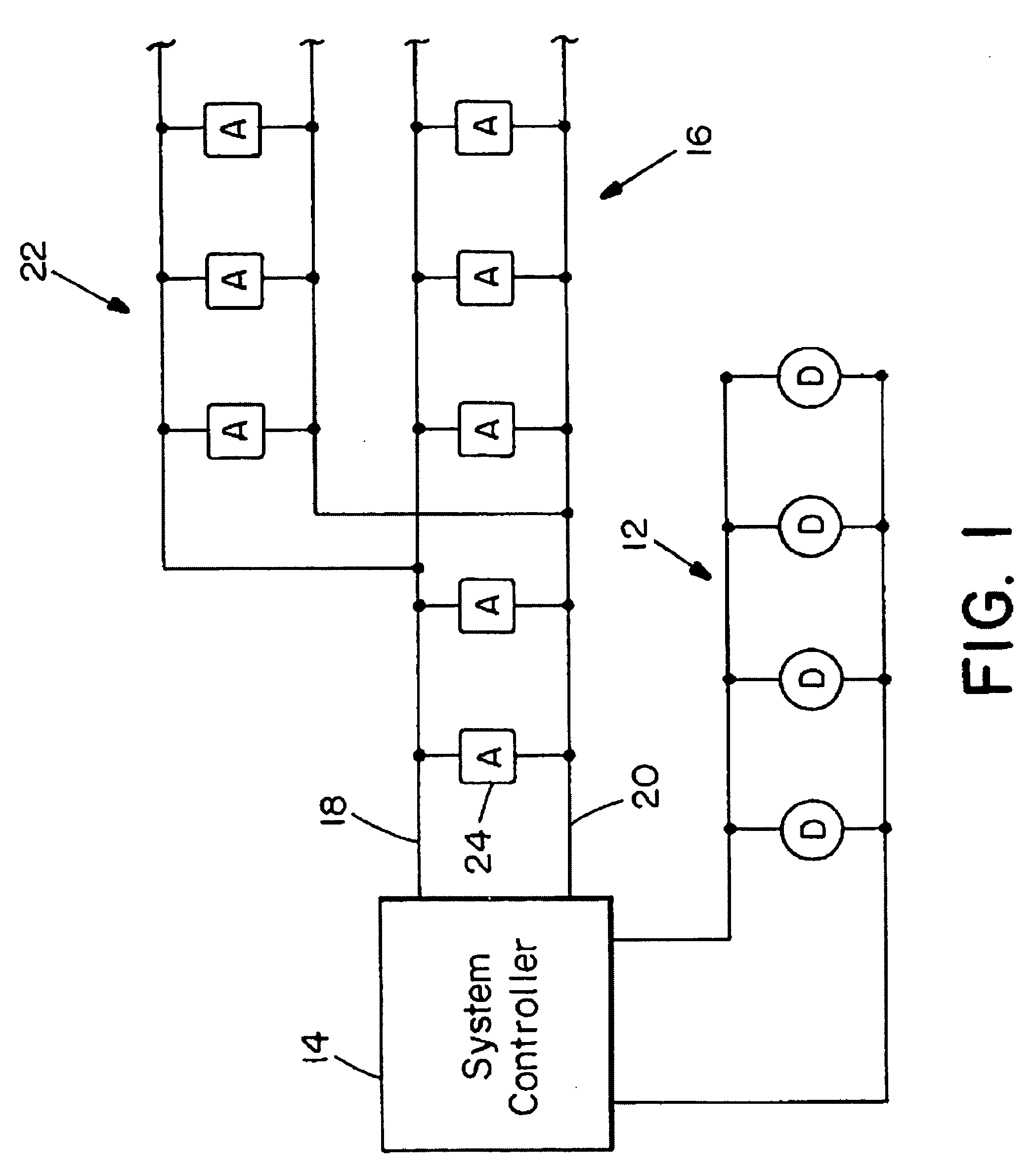
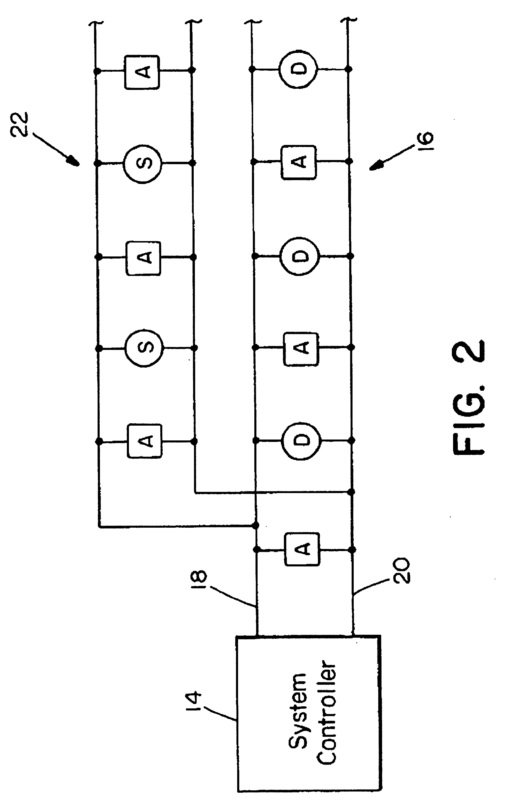
[0035] A system embodying the present invention is illustrated in FIG. 1. As in a conventional alarm system, the system includes one or more detector networks 12 having individual alarm condition detectors D which are monitored by a system controller 14. When an alarm condition is sensed, the system controller 14 signals the alarm to the appropriate devices through at least one network 16 of addressable alarm notification appliances A. Each device, also called a notification appliance 24, may include one or more notification devices, for example, a visual alarm (strobe), an audible alarm (horn), or a combination thereof (A / V device). Also, a speaker for broadcasting live or prerecorded voice messages and a strobe may be combined into a single unit (SN device). A visible indicator (LED) may be provided on any of the above-described notification appliances 24, the LED also controlled by the system controller 14. F...


PUM


Abstract

In a fire alarm system, a message is sent on a pair of power lines to a notification appliance. The notification appliance responds to the message by activating one or more of its notification devices. In a standby mode, only enough power is supplied to the plural notification appliances, at a first voltage level, to support two-way communications between a system controller and the notification appliances. In an active mode, power is supplied at a second voltage sufficient to operate audible and visible alarms of the notification appliance. The notification appliance may include an addressable speaker. The addressable speaker connects to and receives messages over the pair of power lines, has plural taps for selecting audio power. In response to a command, a selector in an addressed smart speaker selects a tap to select a particular audio power.

Description

RELATED APPLICATIONS [0001] This application is a continuation in part of U.S. application Ser. No. 10 / 755,741, filed Jan. 12, 2004, which is a continuation of U.S. application Ser. No. 10 / 156,891, filed May 28, 2002 (now U.S. Pat. No. 6,693,532), which is a continuation of U.S. application Ser. No. 09 / 438,560, filed Nov. 10, 1999 (now U.S. Pat. No. 6,426,697), and is a continuation in part of U.S. application Ser. No. 10 / 873,027, filed Jun. 21, 2004. U.S. application Ser. No. 10 / 755,741, U.S. application Ser. No. 10 / 156,891 (now U.S. Pat. No. 6,693,532), U.S. application Ser. No. 09 / 438,560 (now U.S. Pat. No. 6,426,697) and U.S. application Ser. No. 10 / 873,027 are incorporated herein by reference in their entirety.BACKGROUND OF THE INVENTION [0002] Typical building fire alarm systems include a number of fire detectors positioned throughout a building. Signals from those detectors are monitored by a system controller, which, upon sensing an alarm condition, sounds audible alarms thr...

Claims


Application Information

Patent Timeline
Patent Type & Authority Applications(United States)
IPC IPC(8): G08B21/00
CPCG08B17/00H04R29/007G08B25/06G08B21/023
Inventor CAPOWSKI, ANTHONY J.FURTADO, MICHAEL A.MAIER, PAUL H. JR.KALAFARSKI, STEVEN C.
Owner JOHNSON CONTROLS FIRE PROTECTION LP
Why Eureka
Try Eureka