
Occlusal indicator tray & processes therefor

a technology of occlusal indicator tray and process, which is applied in the field of custom dental trays, can solve the problems of less accurate conformation of trays made with this process to the teeth, and less time for custom dental trays to be formed, so as to facilitate the formation of accurately adapted custom dental trays, less steps, and less time.

Inactive Publication Date: 2007-02-15
KNUTSON ERIC JON
View PDF5 Cites 49 Cited by
  • Summary
  • Abstract
  • Description
  • Claims
  • Application Information

AI Technical Summary

Problems solved by technology

Due to the moderate cost of the specialized vacuum source used in the above process, and the skill of the personnel required, this method of forming custom trays is performed in dental offices or dental laboratories.
In addition, while forming custom trays using this process can be accomplished in a single patient visit, it is much more common for an additional patient visit to be made to deliver the completed trays, due to the amount of time required to complete the trays.
However, trays made with this process tend to be less accurately conformed to the teeth.
Trays made with this process tend to be less accurately conformed to the teeth.
(b) Accurately adapted trays require costly specialized equipment
(c) Accurately adapted trays can require substantial time
(d) Trays formed are not capable of indicating occlusal pressure
(e) Trays formed intraorally tend to have moderate to poor adaptation to the teeth
(f) Trays formed intraorally tend to have moderate to poor retention to the teeth
(g) Trays formed intraorally tend to have substantial fluid leakage
A tray material and process similar to my custom dental tray material and process would not have been as practical prior to the development of low melting polymers, or other materials which are moldable at temperatures which are tolerated intraorally, and then can be caused to become substantially non-moldable.

Method used


Image

  • Occlusal indicator tray & processes therefor
  • Occlusal indicator tray & processes therefor
  • Occlusal indicator tray & processes therefor

Examples


example 1

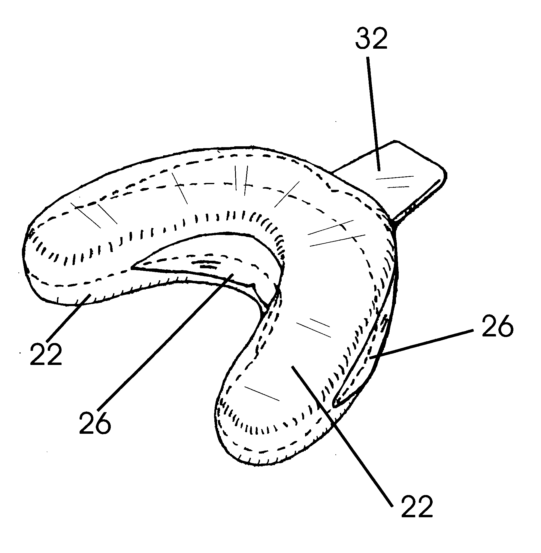
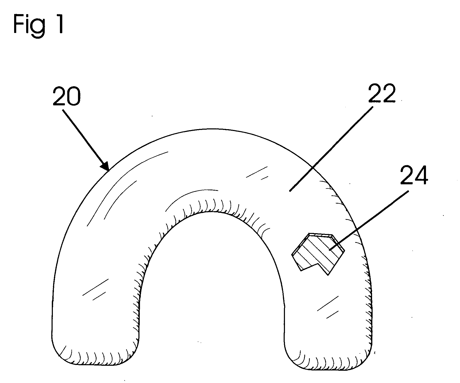
[0113] A first example of a process utilizing basic mouthpiece 20, in this case to form a medicament tray 56, begins with user heating water to 80° C. From a kit provided, user removes a mouthpiece 20 as shown in FIG. 3, a hook for holding mouthpiece 20 underwater, small scissors, and a syringe filled with a medicament.

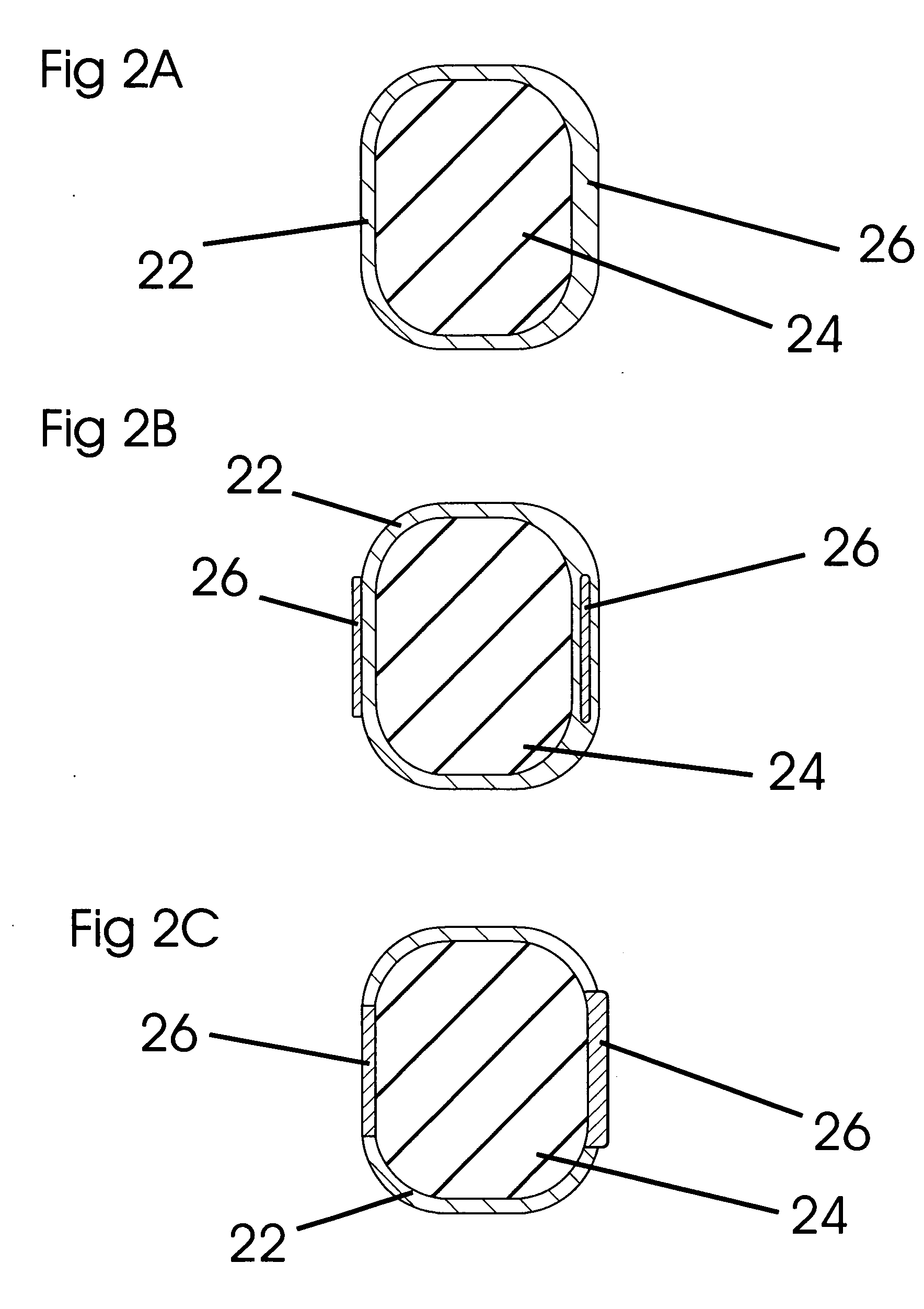
[0114] User places said hook into a small hole in handle 32, and holds said hook to pull basic mouthpiece 20 down into the heated water, as basic mouthpiece 20 tends to float. Basic mouthpiece 20 is held under the heated water until sheet 22 becomes moldable. Basic mouthpiece 20 is removed from the heated water, and is inserted into user's mouth. User forcefully bites the upper and lower arches of teeth into basic mouthpiece 20 until the upper and lower portions of sheet 22 contact separator 28. Filler 24 provides sufficient resistance pressure to mold sheet 22 to fit the shapes of the teeth. Separator 28 inhibits adhesion of the upper portion of sheet 22 to the lowe...

example 2

[0116] A second example of a process utilizing basic mouthpiece 20 as shown in FIG. 1, in this case to hold an attachment, begins with a dentist affixing an attachment, or template thereof, in a patient's mouth, such as by affixing a false tooth in a space left by a missing tooth in a patient's mouth. Said false tooth is affixed into said space in such a way that a small undercut remains under said false tooth, such that sheet 22 can later be molded into said undercut, and thereby retain said false tooth in basic mouthpiece 20, and later in tray 56. A user inserts basic mouthpiece 20 into a rigid dental stock tray. Said stock tray has a wedge-shaped occlusal pad on the surface which will face the opposing dental arch, thereby facilitating forceful occlusion of the teeth onto said stock tray. User heats water to 80° C. Basic mouthpiece 20 is held under the heated water by holding said stock tray handle until sheet 22 becomes moldable. Said stock tray containing basic mouthpiece 20 is...

example 3

[0118] An example of a process utilizing single-arch mouthpiece 38, in this case to form an economical occlusal indicator tray 56, begins with a dental office user selecting a single-arch mouthpiece 38 that is comprised of a sheet 22 containing capsules 46. Said single-arch mouthpiece 38 also has a source 42 comprising an elastic hand-squeezable bulb, as shown in FIG. 7. Said bulb is partly filled with water as a coolant.

[0119] User inserts single-arch mouthpiece 38 in a patient's mouth to check the fit. The curvatures of the patient's dental arches are found to be of slightly different than the curvature of single-arch mouthpiece 38 as provided from the manufacturer. User flexes single-arch mouthpiece 38 to a curvature that corresponds with the arches, and element 40 in single-arch mouthpiece 38 retains the new corresponding curvature.

[0120] Handle 32 is held while immersing single-arch mouthpiece 38 in the heated water until sheet 22 becomes moldable. Source 42 is not immersed i...


PUM


Abstract

An arch-shaped mouthpiece for forming custom dental trays intraorally, which is typically comprised of a sheet of low-melting custom tray material containing a filler, preferably air. The mouthpiece may also have a supporting frame comprised of a facial wall connected to a lingual wall, and a handle. The supporting frame may support the tray material and filler for a single arch, or for both arches. The tray material may contain occlusal pressure indicating means, such as small, rupturable capsules. In typical use, the mouthpiece is heated, the teeth forcefully bite into the tray material and contained filler, thereby molding the tray material to the teeth, the tray material is cooled, the mouthpiece is removed from the teeth, and excess tray material is trimmed away to form a tray.

Description

BACKGROUND—FIELD OF INVENTION [0001] This invention relates to custom dental trays, specifically to custom dental trays that indicate pressure from occlusal contact. BACKGROUND—OCCLUSAL TREATMENT [0002] Splints, stents, and night guards are types of dental appliances which have been fitted with sensors to indicate pressure from occlusal contact. Generally, such appliances are fairly costly and time consuming to fabricate, and are made by a dental laboratory. They are useful for collecting data on dental occlusion, jaw muscle activity during sleep, and so on. Such appliances are primarily used to diagnose or treat patients exhibiting high levels of activity in the muscles of mastication during various stages of sleep, known as bruxism, or mandibular parafunction. Patients generally take such appliances to their homes, and wear them in the mouth during sleep, typically accompanied by one or more data collection or analysis devices. Generally, patients who receive treatment with these ...

Claims


Application Information

Patent Timeline
Patent Type & Authority Applications(United States)
IPC IPC(8): A61C19/04A61C9/00
CPCA61C9/0006A63B71/085A61F5/566A61C19/063
Inventor KNUTSON, ERIC J.
Owner KNUTSON ERIC JON
Learn More