Saw infeed system

a technology of infeed system and saw, which is applied in the direction of manufacturing tools, precision positioning equipment, metal-working machine components, etc., can solve the problems of high maintenance needs, and achieve the effects of low labor cost, safe operation, and ergonomic efficiency

Inactive Publication Date: 2007-02-22
JAMES L TAYLOR MFG
View PDF16 Cites 24 Cited by
  • Summary
  • Abstract
  • Description
  • Claims
  • Application Information

AI Technical Summary

Benefits of technology

[0015] It is another object of this invention to provide a manual loading system that is ergonomically efficient and safely situated for a single person to operate.
[0016] It is another object of this invention to provide an automated infeed system having a low labor cost by reducing the total operation to a single person.

Problems solved by technology

However, these devices have the disadvantage of having high maintenance needs because the longitudinal feeding chains used to propel boards into the saws have to follow a complicated path around and below each clamping device, Another example is U.S. Pat. No. 6,199,463 B1 (Quick), hereby incorporated by reference in its entirety, also assigned to the present assignee, discloses an automated infeed system.

Method used


Image

  • Saw infeed system
  • Saw infeed system
  • Saw infeed system

Examples


Embodiment Construction

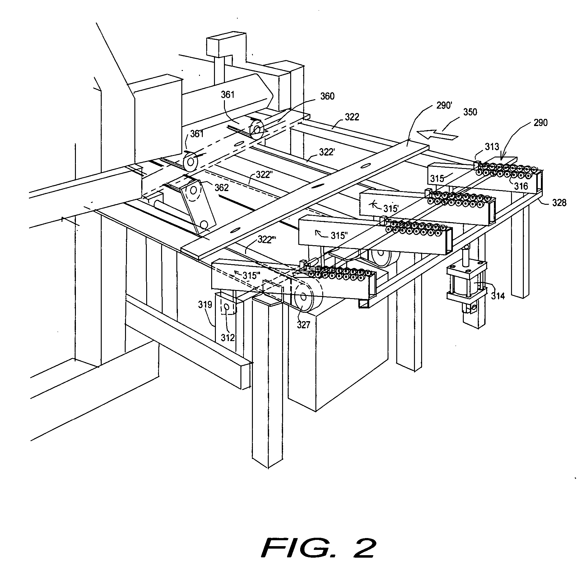
[0028] Referring now to the drawings, in particular to FIGS. 2, 3 and 4. FIG.2 is a perspective illustration, FIGS. 3 and 4 show top and side views respectively, of the automated infeed system constructed according to the principles of the present invention. Shown in the illustrations, an operator 400 removes a workpiece 290 from a supply pile 280 to a ramped roller structure 410, there-in-after, through a pick-up station 420, and continues through a width measuring station 430, projection and optimization area 440, clear area 450 and saw feeding area 460. Fixed arbor gang rip saws 370 are shown in the plan view of FIG. 3. Thus boards 290 to be processed progress from right to left 350 on rollers 316 and belts 322 until they reach the saw area 460. That is, as will be described in more detail shortly, the boards travel broadside in direction 350 until they are picked up by pinch-rollers 361 and 362 at which time they are fed lengthwise in direction 360 into the gang rip saw blades 1...


PUM


Abstract

An apparatus and method for a single operator to load and control the automatic infeeding of workpieces to a saw including the loading of a first workpiece from a nearby supply and placing it onto a moveable structure that that is raised to form a ramp and lowered to release the workpiece. The workpiece moves down the ramp and stops against a stop member located on the top surface of the moveable structure positioned above a first conveyor. The operator controls the lowering of the ramp structure thereupon releasing the workpiece to the first conveyor moving the workpiece transversely past a scanner, which discerns dimensional characteristics of the workpiece. A second conveyor feeds the workpiece into the saw.

Description

BACKGROUND OF THE INVENTION [0001] (1) Technical Field [0002] This invention relates generally to an infeed method and apparatus for conveying individual lengths of woodpieces to wood cutting equipment, and more particularly, to improving the loading of woodpieces onto a servo-driven belt conveyor. [0003] (2) Description of the Prior Art [0004] The following 5 documents relate to apparatus for infeeding articles onto a conveyor for transport. [0005] U.S. Pat. No. 6,305,525 issued Oct. 23, 2001 to Miller et al. describes a pressureless infeed conveyor for establishing a spacing between articles on a conveyor having reciprocating carriages driven by a reversible servo-motor. [0006] U.S. Pat. No. 6,199,463 issued Mar. 13, 2001 to Quick describes an apparatus and methodology for infeeding workpieces to a saw. [0007] U.S. Pat. Nos. 5,368,080 issued Nov. 29, 1994 to Hamel describes an apparatus and related method for a board edging infeed optimization system. [0008] U.S. Pat. No. 4,874,08...

Claims


Application Information

Patent Timeline
Patent Type & Authority Applications(United States)
IPC IPC(8): B27B1/00B23Q15/00B23Q16/00
CPCB27B31/003B27B31/06B27B31/006
Inventor QUICK, BRADLEY
Owner JAMES L TAYLOR MFG
Why Eureka
Try Eureka