

LED-based luminaire
a technology of led luminaires and leds, which is applied in the direction of lighting support devices, coupling device connections, light sources, etc., can solve the problems of not having long operating lifetimes, high power requirements of bulbs, and frequent replacement, so as to reduce costs, simplify and standardize led luminaires, and maximize led lighting
- Summary
- Abstract
- Description
- Claims
- Application Information
AI Technical Summary
Benefits of technology
Problems solved by technology
Method used
Image

Examples
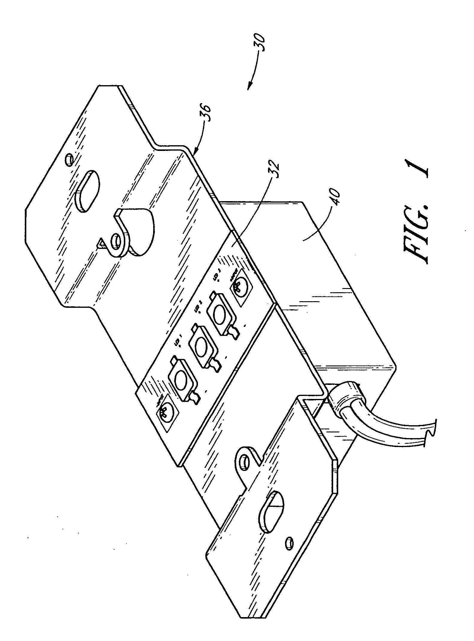
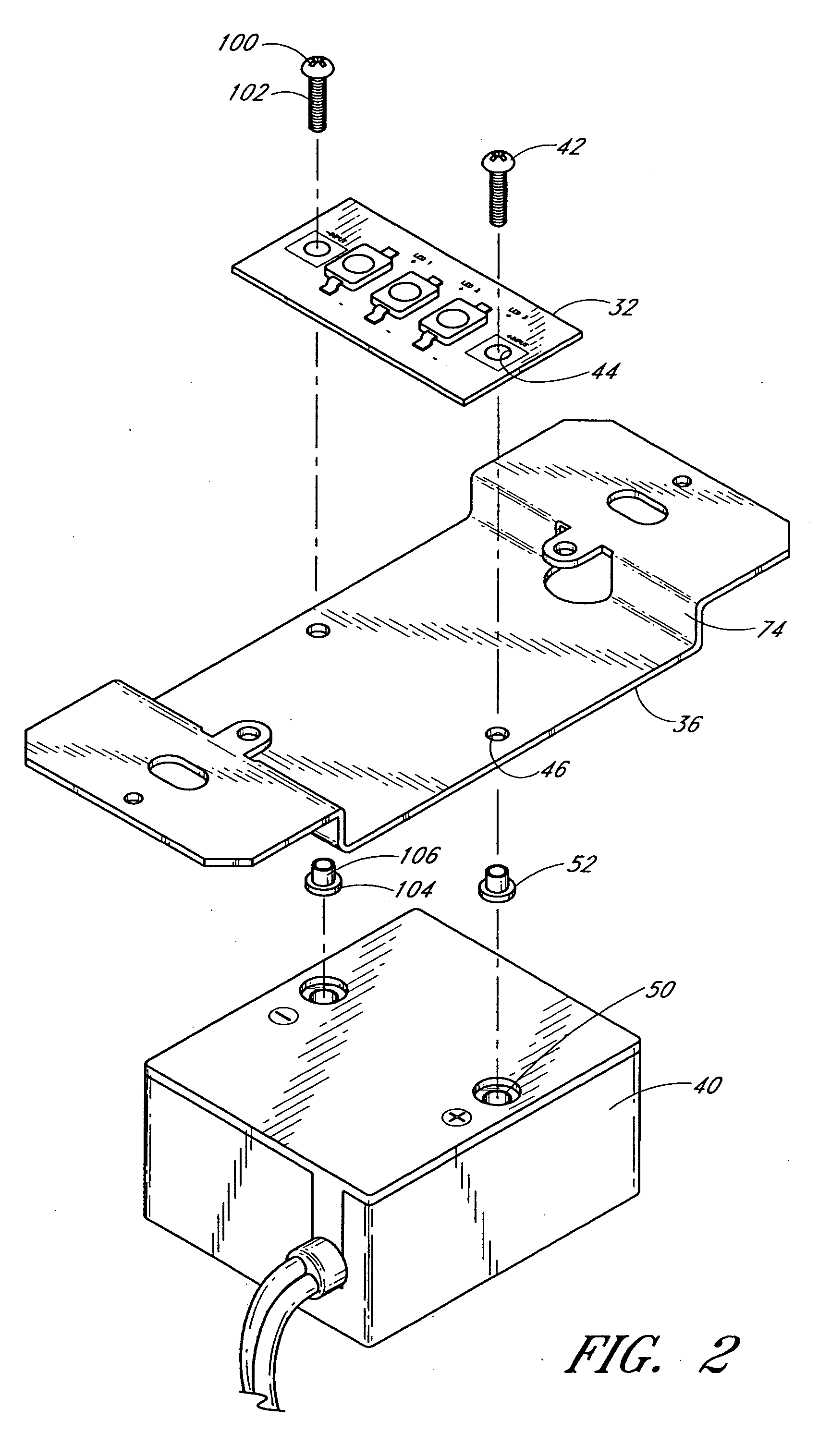
embodiment 30
[0047] The rectangular geometry of the illustrated embodiment is especially suitable for the illustrated luminaire embodiment 30 discussed herein. It is to be understood, however, that other embodiments may benefit from differing module configurations. For example, it is contemplated that modules may be square, circular, oval, irregularly-shaped or may have widely varying rectangular dimensions (such as being especially long and thin). Additionally, although the illustrated modules are relatively flat, it is understood that other embodiments may include modules having simple or complex three dimensional shapes.
[0048] With continued reference to FIG. 3, the body 54 of the lighting module 32 can be made of various materials, rigid or flexible. However, most preferably, the body comprises a generally rigid heat conductive material such as aluminum. Preferably, the body 54 is constructed of a material having high heat conductance properties such as a heat conductivity greater than about...
embodiment 130
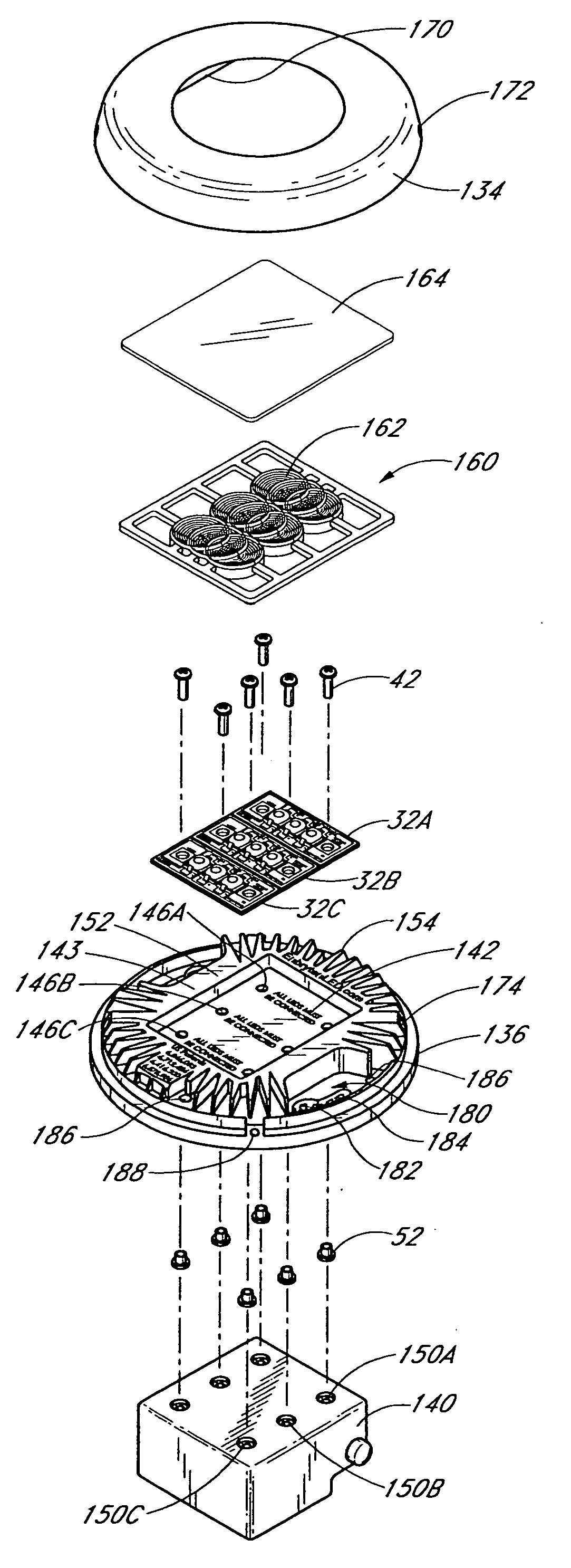
[0069]FIG. 7 presents an exploded view of the embodiment illustrated in FIG. 6 but not showing the back housing. As shown, the illustrated embodiment 130 employs three LED-based lighting modules 32A-C that are configured to fit in a module mounting portion 142 of the mount base 136. The module mounting portion 142 is specifically configured to accommodate all three modules 32A-C. As shown, the module mounting portion 142 of the base 136 is offset from a front surface 143 of the base so that the lighting modules are offset inwardly relative to the front surface 143. Additionally, the mounting portion 142 is shaped so as to complement the shape of the lighting modules 32A-C. In the illustrated embodiment, the module mounting portion 142 is substantially rectangular and flat-surfaced so as to complementarily accommodate the lighting modules. Module apertures 44 are formed through each lighting module 32, and three pairs of mounting base apertures 146A-C are formed through the mounting ...
PUM
 Abstract
Description
Claims
Application Information