
Diverter valve for water systems

Inactive Publication Date: 2007-03-01
SPECIALTY PLASTICS APPL
View PDF9 Cites 81 Cited by
  • Summary
  • Abstract
  • Description
  • Claims
  • Application Information

AI Technical Summary

Problems solved by technology

The sharp bend, or turn, results in a pressure drop, in addition to causing turbulent flow and noise.

Method used


Image

  • Diverter valve for water systems
  • Diverter valve for water systems
  • Diverter valve for water systems

Examples


Embodiment Construction

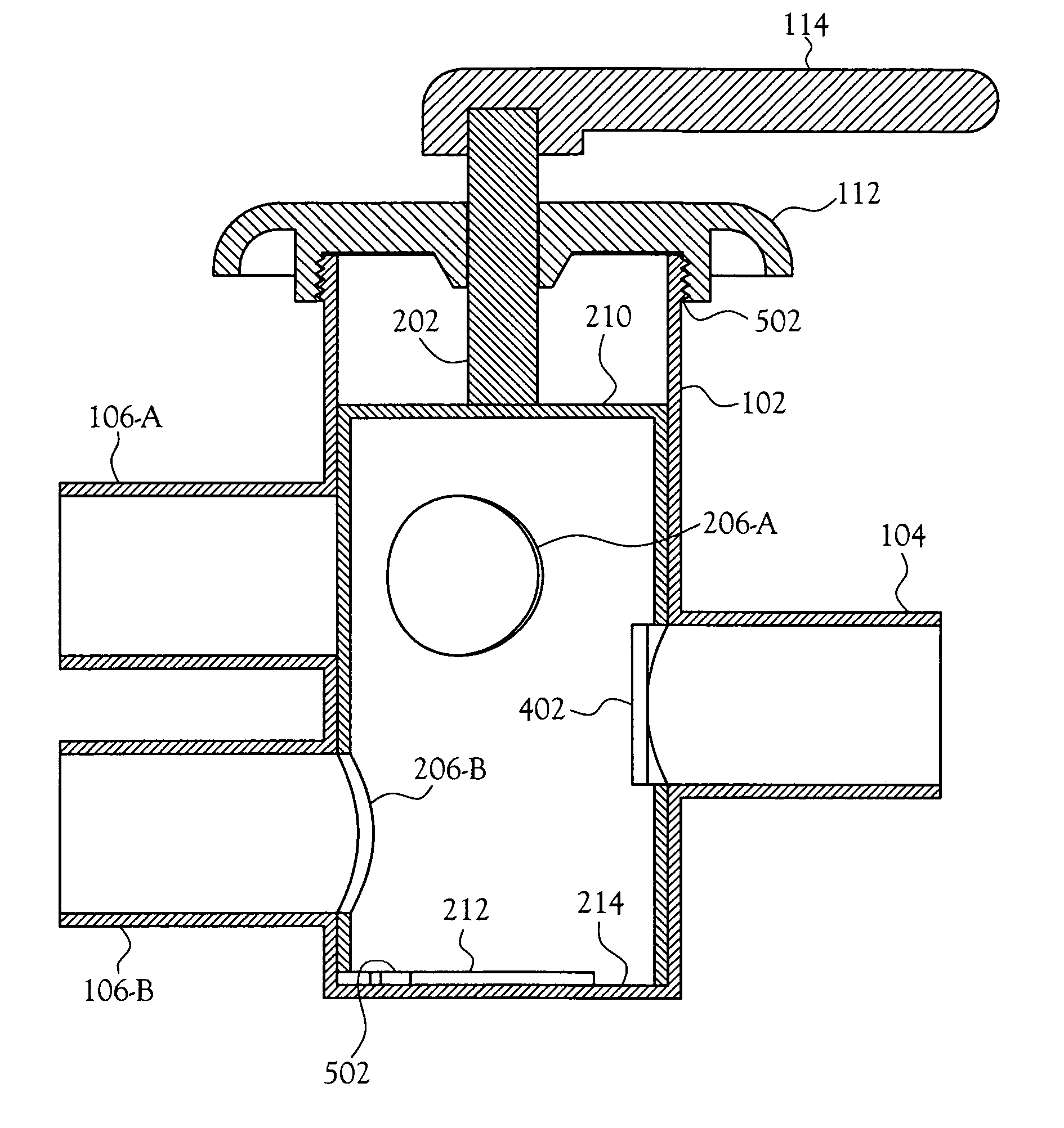
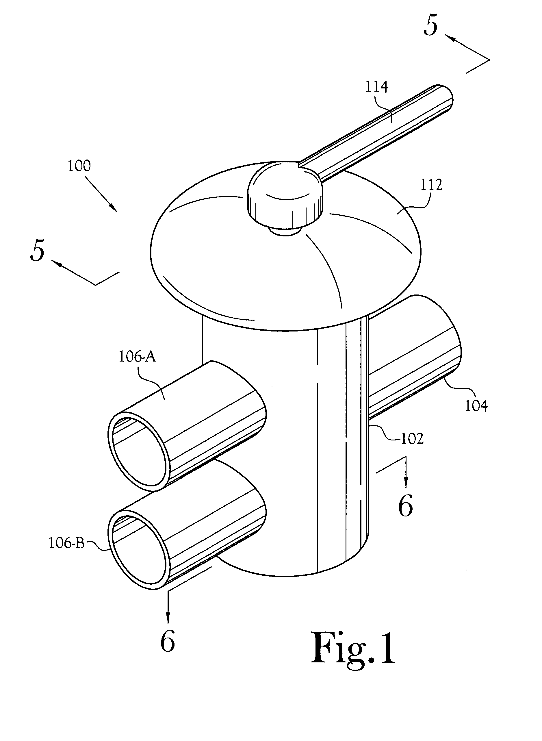
[0018] An apparatus for diverting water flow is disclosed. The apparatus is generally shown as item 100 on the figures. The illustrated diverter valve 100 is a two position valve with a single port 104 switchable to one of two ports 106.

[0019]FIG. 1 illustrates a perspective view of one embodiment of a diverter valve 100. The valve 100 has a valve body 102 with one inlet port 104 and two outlet ports 106-A, 106-B. Those skilled in the art will recognize that the direction of water flow relative to the valve 100 is immaterial, for example, in another embodiment the valve body 102 has two inlet ports 106-A, 106-B and one outlet port 104.

[0020] In the illustrated embodiment, the ports 104, 106 are pipe stubs suitable for attaching sections of pipe. For example, the diverter valve 100 is fabricated of polyvinyl chloride (PVC) material and additional pipe sections are fused to the ports 104, 106 to form a waterproof, sealed connection. In other embodiments, the ports 104, 106 have flan...


PUM


Abstract

An apparatus for diverting water flow between a single port and at least a pair of ports. The diverter valve includes a single port on one side of a valve body and a pair of ports on the opposite side of the cylindrical valve body. The diverter member inside the valve body rotates between two positions when an operator is moved. At either of the two positions, the diverter member aligns one of a pair of openings with one of the pair of ports, thereby allowing fluid to flow between the single port and one of the pair of ports. In various embodiments, the pair of openings are positioned such that, between the two positions, there is no flow or limited flow through one or both of the pair of ports.

Description

CROSS-REFERENCE TO RELATED APPLICATIONS [0001] Not Applicable STATEMENT REGARDING FEDERALLY SPONSORED RESEARCH OR DEVELOPMENT [0002] Not Applicable BACKGROUND OF THE INVENTION [0003] 1. Field of Invention [0004] This invention pertains to diverter valve for a fluid system. More particularly, this invention pertains to valve that diverts water from one flow path to another flow path, while minimizing the back pressure when changing from one flow path to another. Such a diverter valve is used in pools, spas, hot tubs, bathtubs to divert water flow from the pumps to the jets. [0005] 2. Description of the Related Art [0006] Diverter valves direct water from one or more pumps to different groupings of jets in pools, spas, hot tubs, and bathtubs. The prior art includes several types of diverter valves. For example, U.S. Pat. No. 4,800,046, issued to Malek, et al., on Jan. 24, 1989, titled “Water jet aerator with diverter valve,” and U.S. Pat. No. 4,218,784, issued to Richards on Aug. 26, ...

Claims


Application Information

Patent Timeline
IPC IPC(8): F16K11/085
CPCF16K11/0856Y10T137/86871
Inventor BONIOR, DAVID
Owner SPECIALTY PLASTICS APPL
Features
  • Generate Ideas
  • Intellectual Property
  • Life Sciences
  • Materials
  • Tech Scout
  • Unparalleled Data Quality
  • Higher Quality Content
  • 60% Fewer Hallucinations
Learn More