Pull out extension contained in electrical box

Active Publication Date: 2007-03-01
THOMAS & BETTS INT INC
View PDF90 Cites 8 Cited by
  • Summary
  • Abstract
  • Description
  • Claims
  • Application Information

AI Technical Summary

Benefits of technology

[0008] Applicant has overcome the shortcomings of prior art electrical outlet boxes by providing an extension device that can be installed within the electric

Problems solved by technology

However, in some applications the offset is insufficient to bring the open face of the box flush with the finish materia

Method used


Image

  • Pull out extension contained in electrical box
  • Pull out extension contained in electrical box
  • Pull out extension contained in electrical box

Examples


Example

[0024] There will be detailed below the preferred embodiments of the present invention with reference to the accompanying drawings. Like members are designated by like reference characters in all figures.

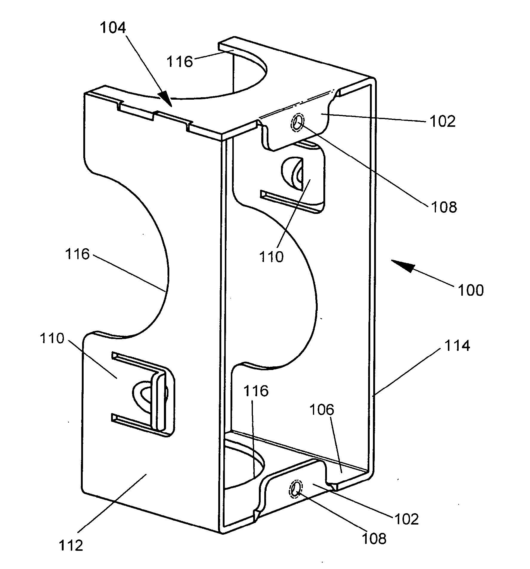
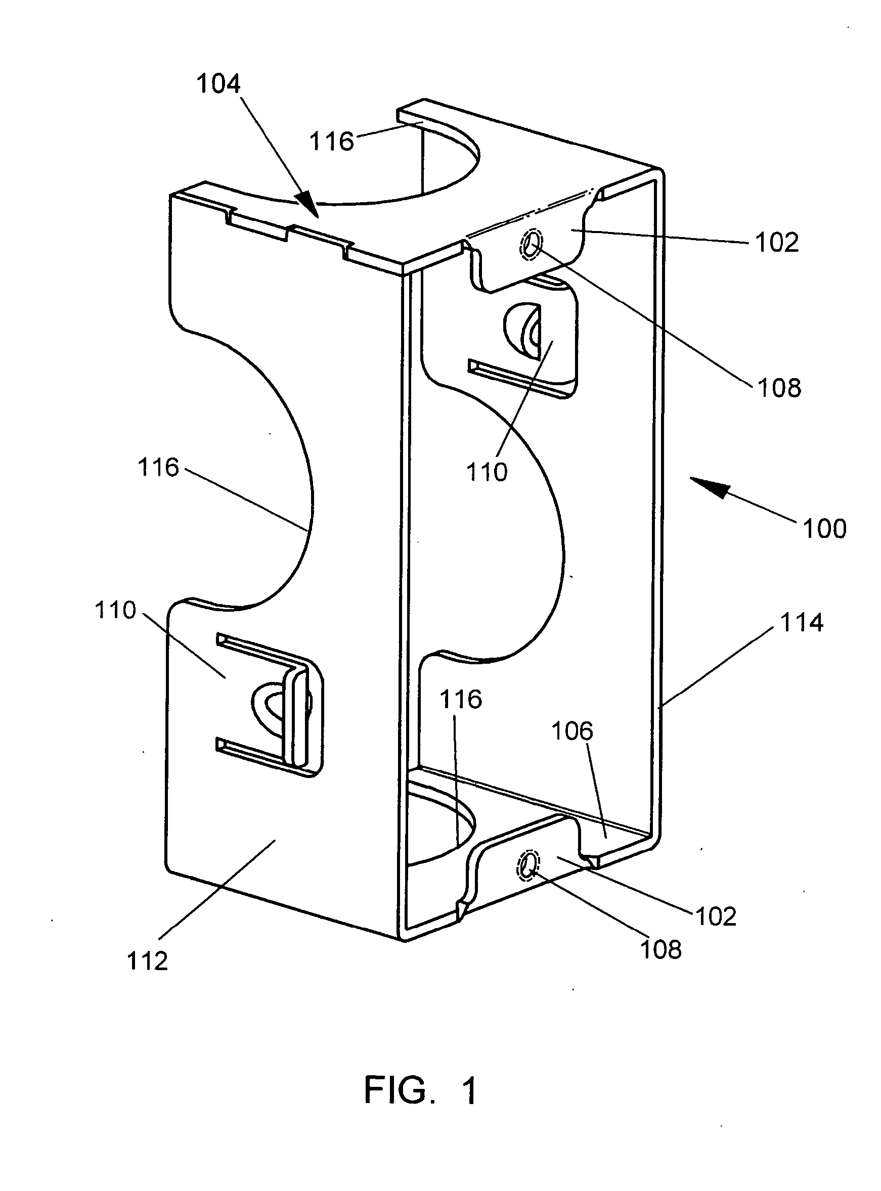
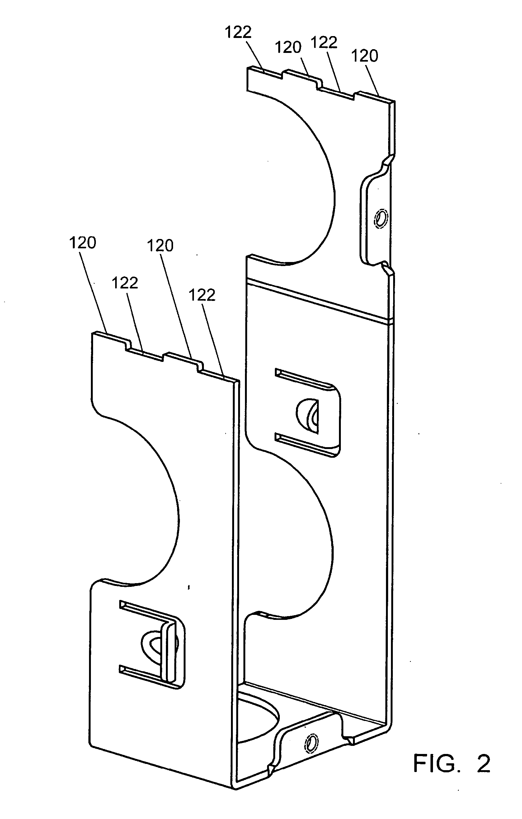
[0025] Turning now to FIGS. 1 and 2, there is shown a perspective view of the outlet box extension according to the present invention. The extension, which is a generally rectangular frame 100, typically made of a metallic material, which may be a folded sheet metal. The extension has ears 102 located on the top 104 and bottom walls 106, each having tapped holes 108 for mounting an electrical device within the electrical box. Because the ears 102 and holes 108 are mounted on the extension frame 100 the holes 108 are closer to the device that will be installed in the extension allowing the use of shorter screws which provide a stronger and more stable mounting within the electrical box. The extension is held in place by tabs 110, which are resilient deformable structures that protru...


PUM


Abstract

An electrical outlet box extension comprising a perimetrical side wall with an inner surface and an outer surface having an open front face and an open rear face and defining an interior space, and having at least one outwardly protruding resilient tab located on the side wall outer surface. The box extension is designed for adjustable insertable receipt within an electrical outlet box for increasing the depth of the box.

Description

CROSS-REFERENCE TO RELATED APPLICATION: [0001] This application claims priority to U.S. Provisional Patent Application No. 60 / 713,121, filed on Aug. 31, 2005, which is incorporated herein by reference.FIELD OF THE INVENTION [0002] The present invention relates generally to a pull out extension contained in an electrical outlet box for housing electrical fixtures such as a switch or a receptacle. More particularly, the present invention relates to an extension for increasing the depth of an electrical box in certain applications such as for use on a concrete wall. BACKGROUND OF THE INVENTION [0003] It has long been known to house electrical fixtures such as switches and receptacles in an electrical outlet box. The outlet box permits the insertion of electrical wires into the box which are terminated to electrical fixtures. The fixtures then may be mounted to the box which provides protection to the fixtures as well as the wires terminated therein. The outlet box is then mounted to a ...

Claims


Application Information

Patent Timeline
IPC IPC(8): H02G3/08
CPCH02G3/086
Inventor LALANCETTE, DANIELLUPSA, IOAN LIVIU
Owner THOMAS & BETTS INT INC
Why Eureka
Try Eureka