

Shutter border frame with channel and cover plug
- Summary
- Abstract
- Description
- Claims
- Application Information
AI Technical Summary
Benefits of technology
Problems solved by technology
Method used
Image

Examples
Embodiment Construction
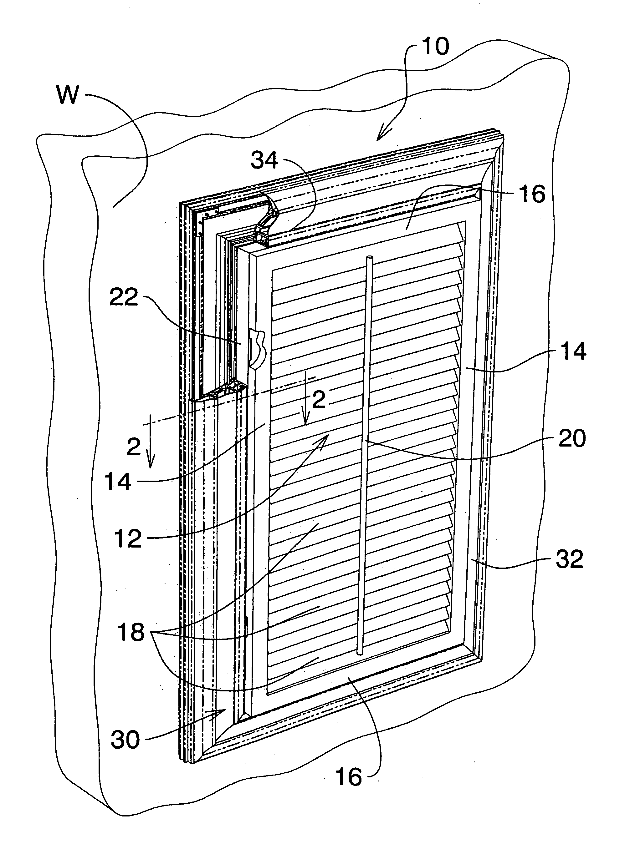
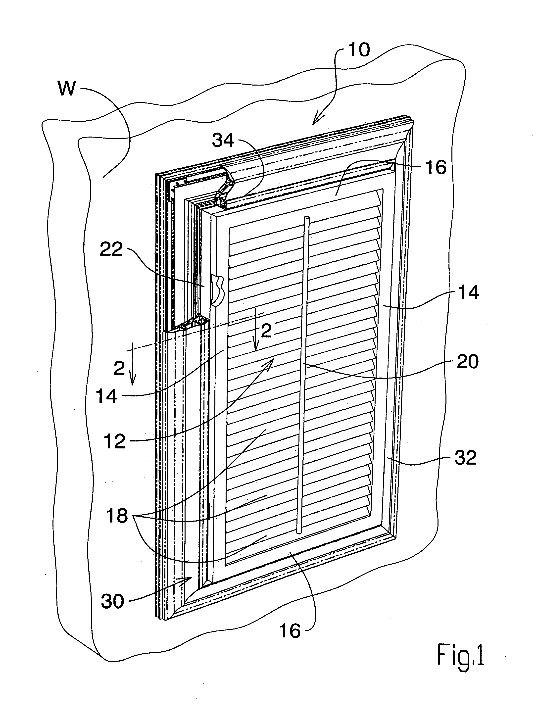
[0038]A shutter assembly (10) shown in FIG. (1), illustrating an embodiment of invention, is shown installed in registration with a window (or a door) (W). In the context of this description, although the description which follows discloses the shutter as installed in a window (W), it should be understood that the shutter assembly (10) with minor modifications can be installed in a doorway.
[0039]FIG. 1 shows the shutter (12) being comprised of a pair of vertically opposed side portions (14) and a pair of horizontally opposed side portions (16). The shutter (12) also includes a plurality of horizontal louvres (18) mounted between opposed vertical side portions (14). A louvre usually is hollow extrusion of suitable plastic as shown on FIG. 1. Each louvre (18) has a pivot pin on each end (not shown) received in the vertical side portions (14). The vertical side portions (14) include a plurality of louvre pivot pin openings (not shown). The tilt of the louvres can be adjusted by the til...
PUM
 Abstract
Description
Claims
Application Information