Image processing system, image processing apparatus, image processing method and medical image diagnosis apparatus

An image processing device and image processing technology, which are applied in special data processing applications, instruments for radiological diagnosis, diagnosis, etc., can solve problems such as the limit of image depth, and achieve the effect of improving the depth.

Inactive Publication Date: 2013-01-23
TOSHIBA MEDICAL SYST CORP
View PDF7 Cites 6 Cited by
  • Summary
  • Abstract
  • Description
  • Claims
  • Application Information

AI Technical Summary

Problems solved by technology

However, in conventional technologies, there is a limit to the

Method used


Image

  • Image processing system, image processing apparatus, image processing method and medical image diagnosis apparatus
  • Image processing system, image processing apparatus, image processing method and medical image diagnosis apparatus
  • Image processing system, image processing apparatus, image processing method and medical image diagnosis apparatus

Examples


Example

[0027] (First Embodiment)

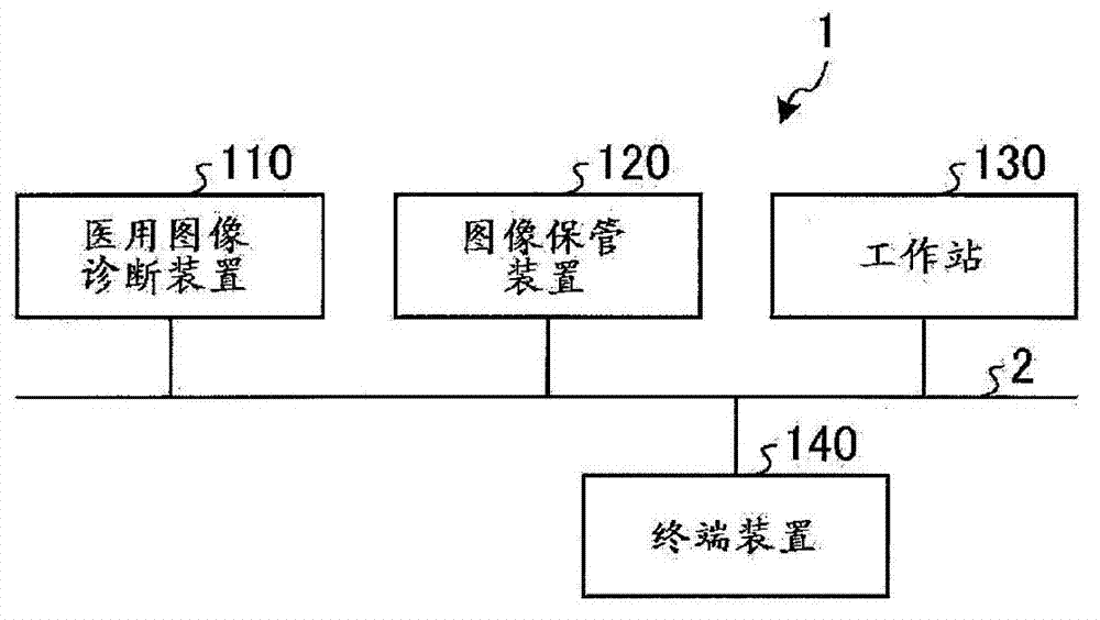
[0028] First, a configuration example of the image processing system according to the first embodiment will be described. figure 1 It is a diagram for explaining a configuration example of the image processing system according to the first embodiment.

[0029] Such as figure 1 As shown, the image processing system 1 according to the first embodiment includes a medical image diagnosis device 110, an image storage device 120, a workstation 130, and a terminal device 140. figure 1 The illustrated devices are in a state where they can directly or indirectly communicate with each other via an in-hospital LAN (Local Area Network) 2 installed in a hospital, for example. For example, when PACS (Picture Archiving and Communication System) is introduced to the image processing system, each device sends and receives medical images to each other in accordance with the DICOM (Digital Imaging and Communications in Medicine) standard.

[0030] The image processing system...

Example

[0105] (Second Embodiment)

[0106] In the first embodiment described above, a description has been given of the case where parallax images with different viewpoint positions are alternately switched and displayed with the same pixel. In the second embodiment, a case where the shift between parallax images displayed on the same pixel is corrected and displayed will be described. In addition, in the second embodiment, Picture 10 The control unit 135 according to the illustrated first embodiment has the same configuration. Therefore, in the second embodiment, the control unit that corrects the shift between the parallax images displayed on the same pixel is described as the display control unit 1352a. That is, the display control unit 1352a Picture 10 New processing is added to the display control unit 1352 shown.

[0107] Here, first, for the outline of the correction process executed by the display control unit 1352a, use Figure 14 Be explained. Figure 14 It is a schematic di...

Example

[0124] (Third Embodiment)

[0125] Then, the first and second embodiments are described here, but in addition to the above-mentioned first and second embodiments, it may be an embodiment implemented in various different ways.

[0126] In the second embodiment described above, the case where the pixel value is used to correct the shift of the parallax image has been described, but the shift of the parallax image can also be corrected by sliding the lenticular lens in synchronization with the timing of switching the parallax image. Figure 17 It is a diagram for explaining the offset correction based on the sliding of the lenticular lens according to the third embodiment. in Figure 17 In Figure 12B When the parallax image is switched, the lenticular lens is slid.

[0127] When the offset is corrected by sliding the lenticular lens, for example, the display section 132 has a driving device for sliding the lenticular lens. As an example, the display unit 132 has a vibration generati...


PUM


Abstract

The invention relates to an image processing system, an image processing apparatus, an image processing method and a medical image diagnosis apparatus which can improve the depth degree of stereoscopic observation images. In the image processing apparatus of the invention, a display unit displays a specified number of parallax images simultaneously; a parallax image generation control unit performs control so as to generate a parallax image group with viewpoint positions more than the specified number; and a display control unit performs control so as to divide the parallax image group into a first part parallax image group containing a group of parallax images of discontinuous viewpoint positions and a second part parallax image group containing parallax images of viewpoint positions between the group of parallax images, and switch and display the first and second part parallax image groups at a specified switch speed.

Description

[0001] This application claims the priority of Japanese Patent Application No. 2011-160071 filed on July 21, 2011, and uses all the contents of the above-mentioned Japanese Patent Application in this application. Technical field [0002] The present invention relates to an image processing system (system), a device, a method, and a medical image diagnosis device. Background technique [0003] In the past, a monitor that can stereoscopically observe two-parallax images taken from two viewpoints using dedicated equipment such as stereoscopic glasses is being put into practical use. In addition, in recent years, a display that can stereoscopically observe multi-parallax images (for example, 9-parallax images) captured from multiple viewpoints with the naked eye using light control elements such as lenticular lenses has been put into practical use. In addition, a 2-parallax image or a 9-parallax image displayed on a stereoscopic display may be generated by image processing that estima...

Claims


Application Information

Patent Timeline
IPC IPC(8): G06F19/00A61B5/055A61B8/00A61B6/00A61B6/03
CPCH04N13/0275G09G5/14H04N13/045H04N13/0447H04N13/0438H04N13/275H04N13/341H04N13/351H04N13/354
Inventor 塚越伸介原拓实
Owner TOSHIBA MEDICAL SYST CORP
Why Eureka
Try Eureka