Pneumatically driven setting tool

a technology of pneumatic drive and setting tool, which is applied in the direction of manufacturing tools, nailing tools, tapering tools, etc., can solve the problems of large tool space occupied by compressors and expansion chambers, and achieve the effect of reducing the construction volume of setting tools

Active Publication Date: 2007-03-01
HILTI AG
View PDF10 Cites 95 Cited by
  • Summary
  • Abstract
  • Description
  • Claims
  • Application Information

AI Technical Summary

Benefits of technology

[0011] The novel features of the present invention permit to noticeably reduced the constructional volume of the inventive setting tool.
[0013] Advantageously, the setting tool has a control unit connected by a control conductor with the piston retaining device which the control unit controls. This permits to make available a maximum possible amount of the setting energy. This is because the control unit can actuate the piston retaining device at an optimal time point after actuation of the actuation switch.
[0014] Advantageously, the compression device has at least one cylinder arranged sidewise of the common chamber, at least one compression piston displaceable in the cylinder, a motor for driving the compression piston, and a transmission element for transmitting torque from the motor to the compression piston. The foregoing arrangement permits to further reduce the constructional volume of the setting tool.
[0015] It is further advantageous when the cylinder extends coaxially to a longitudinal axis of the setting tool and which is defined by the drive-in piston. In this way, the length of the expansion chamber can be used for the stroke of the compression piston.
[0016] According to a preferable embodiment of the invention, a compression member is displaceably arranged in the housing in which the chamber is located. This arrangement of the compression member permits to eliminate a separate chamber for the compression cylinder.

Problems solved by technology

A drawback of the setting tool, which is disclosed in the above-mentioned U.S. publication, consists in that the compressor, together with the expansion chamber, occupy a large volume of the tool space.

Method used


Image

  • Pneumatically driven setting tool
  • Pneumatically driven setting tool
  • Pneumatically driven setting tool

Examples


Embodiment Construction

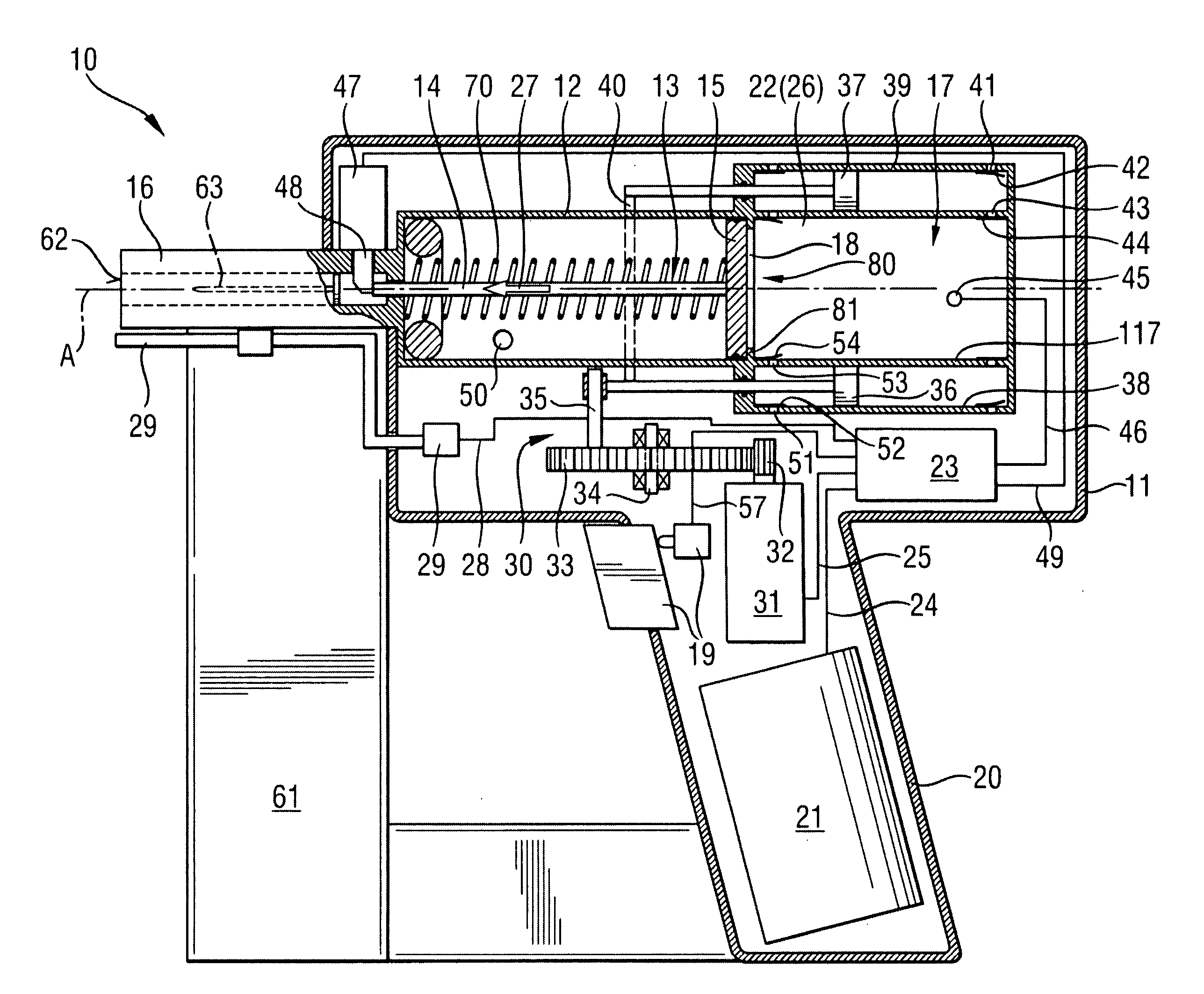
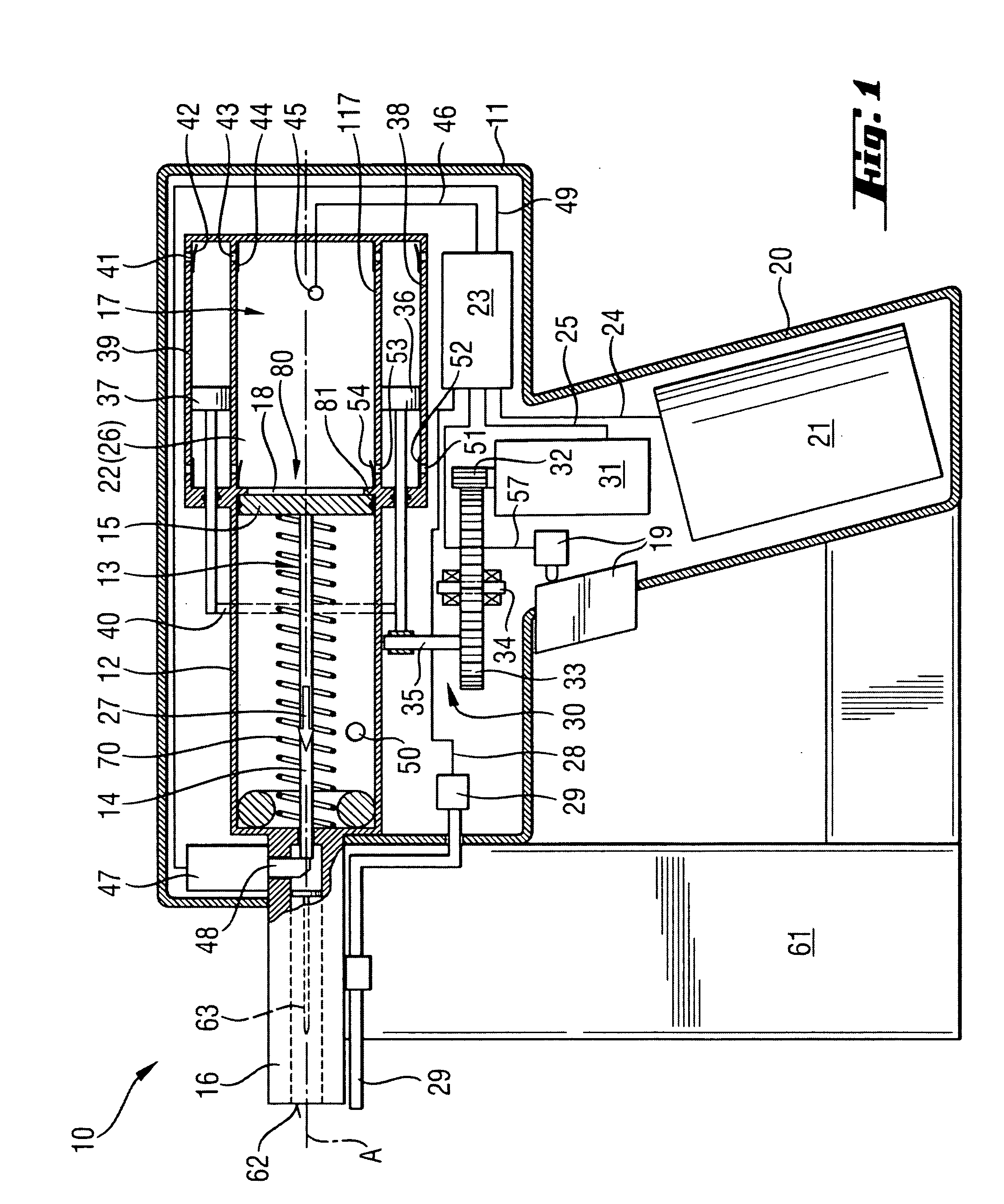
[0026] A pneumatic setting tool 10 according to the present invention, which is shown in FIG. 1, includes a housing 11 in which a setting mechanism with a drive-in piston 13 is located. The drive-in piston 13 is displaceable in a cylindrical guide 12. The drive-in piston 13 has a piston head 15 and a piston stem 14 extending from the piston head 15 in a direction of a bolt guide 16 that adjoins the cylindrical guide 12. At the end of the guide 12 remote from the bolt guide 16, there is provided a housing 117 having a chamber 17 that communicates with the guide 12 through an opening 18. The opening 18 is surrounded by a circumferential projection 81 which the piston head 15 engages in its initial position 80 shown in FIG. 1. In the initial position 80, the drive-in piston 13 is retained by a piston holding device 47. The piston holding device 47 has a locking member 48 that projects in the bolt guide 16 and blocks the piston stem 14. The piston holding device 47 is formed, e.g., as a...


PUM


Abstract

A pneumatically driven setting tool for driving in fastening elements, includes a chamber (17) forming a storage chamber (22) for storing the pressure medium produced by the compression device (30, 130) and an expansion chamber (26) adjoining the drive-in piston (13), which is displaceable in a guide (12), at a side of the drive-in piston (13) remote from the piston stem (14), communicating with the storage chamber (22), and having an opening (18) connecting the expansion chamber (26) with the drive-in piston (13), at least one check valve (44, 54, 142) arranged between the compression device (30, 130) and the chamber (17), and a piston retaining device (47) for retaining the drive-in piston (13) in its initial position (80) in which the chamber (17) is sealed against the guide (12).

Description

BACKGROUND OF THE INVENTION [0001] 1. Field of the Invention [0002] The present invention relates to a pneumatically driven setting tool including a drive-in piston displaceably supported in the guide, driven by a gaseous pressure medium, and having a piston stem, a compression device for providing the gaseous pressure medium for driving the drive-in piston, a storage chamber for storing the pressure medium produced by the compression device, and an expansion chamber adjoining the drive-in piston at a side of the drive piston remote from the piston stem, communicating with the storage chamber, and having an opening connecting the expansion chamber with the drive-in piston. [0003] 2. Description of the Prior Art [0004] With setting tools described above, fastening elements are driven in a constructional component as a result of drive-in movement of a setting or drive-in piston. In these pneumatically driven setting tools, the setting or drive-in piston is accelerated by an expandable...

Claims


Application Information

Patent Timeline
Patent Type & Authority Applications(United States)
IPC IPC(8): B25C1/04B25C5/06
CPCB25C1/06B25C1/04
Inventor TOWFIGHI, KAVEH
Owner HILTI AG
Why Eureka
Try Eureka