Design method and design system for roof rainwater drainage systems and drainage system

A technology of drainage system and design method, applied in the field of water supply and drainage of buildings, can solve problems such as poor drainage and water leakage

Active Publication Date: 2011-11-09
CHINA IPPR INT ENG
View PDF4 Cites 13 Cited by
  • Summary
  • Abstract
  • Description
  • Claims
  • Application Information

AI Technical Summary

Problems solved by technology

Therefore, in the design of roof drainage system based on one-phase flow of water, when two-phase flow occurs, due to the aeration of water flow, the gas will occupy part of the cross-section of the suspension pipe, standpipe and buried rainwater pipe, resulting in drainage If it is not smooth, it is easy to cause roof water and / or buried pipe inspection well water accidents

Method used


Image

  • Design method and design system for roof rainwater drainage systems and drainage system
  • Design method and design system for roof rainwater drainage systems and drainage system
  • Design method and design system for roof rainwater drainage systems and drainage system

Examples


Embodiment Construction

[0113] In order to enable those skilled in the art to better understand the technical solution of the present invention, the design method of the roof rainwater drainage system provided by the present invention will be described in detail below in conjunction with the drawings and specific embodiments.

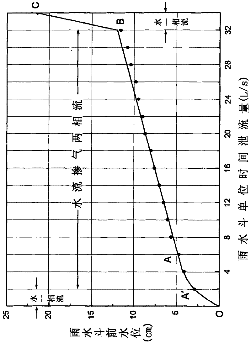
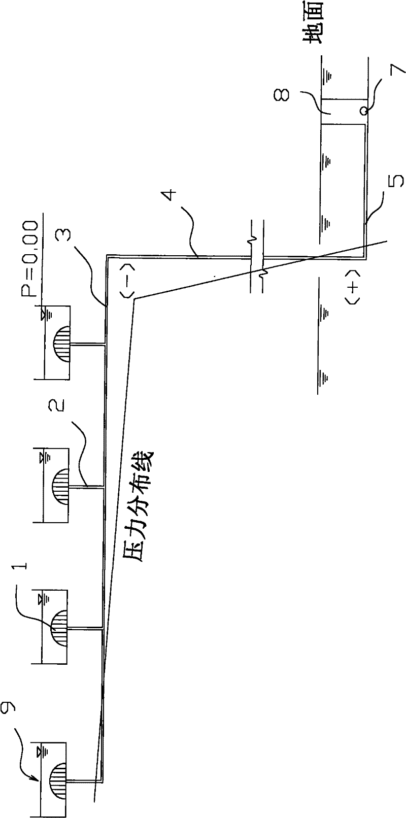
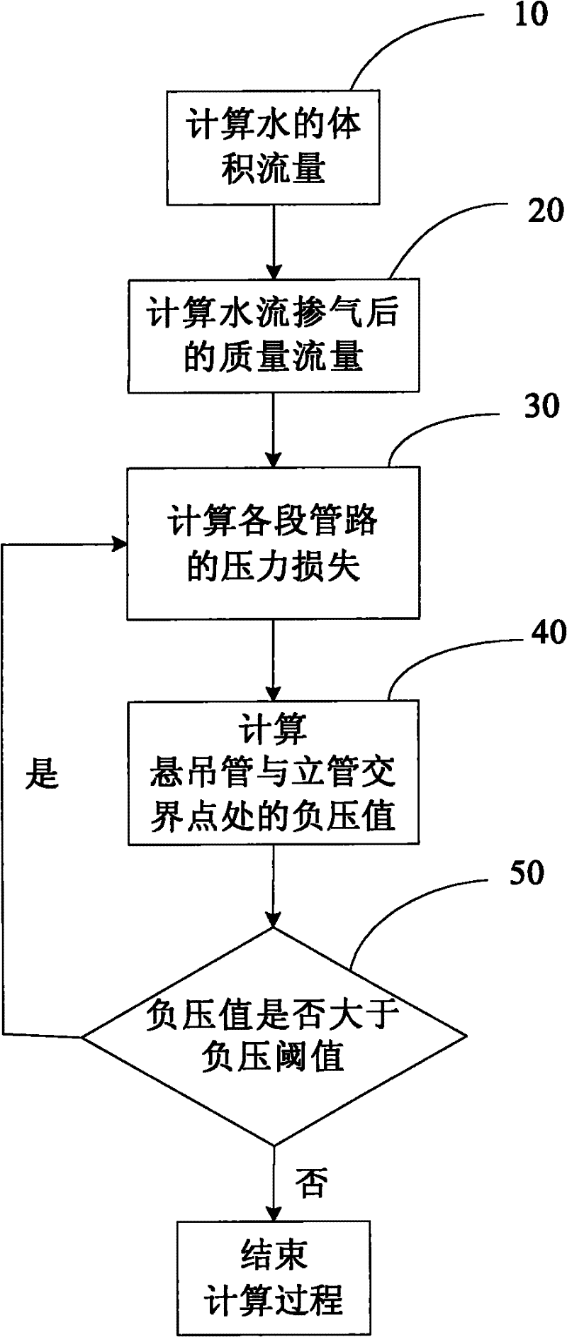
[0114] In the design method of the roof rainwater drainage system of the present invention, the two-phase flow situation that occurs after the rainwater bucket is aerated during the drainage process of the roof rainwater is considered. Calculate the pressure loss of each section of the pipeline based on the mass flow rate after the gas, and then determine the pipe diameter value according to the negative pressure value and pressure loss, so as to design the rainwater drainage system of the entire house.

[0115] Specifically, see image 3 The design method flowchart of roof rainwater drainage system of the present invention, the design method of roof rainwater drainage system ...


PUM


Abstract

The invention provides a design method for roof rainwater drainage systems, which comprises the following steps of: calculating the volumetric flow rate of water flowing through a rainwater hopper; calculating the mass flow rate of an aerified water flow; calculating the pressure loss of each pipeline section based on the mass flow rate of the aerified water flow; calculating the values of negative pressures on a hanged pipe and a stand pipe at the junction point of the tail end of the hanged pipe and the top end of the stand pipe; judging whether the values of negative pressures on the hanged pipe and the stand pipe at the junction point satisfy the design requirements of a pipe system or not, if so, completing the design process; and otherwise, designing the value of each pipe diameter again, and then calculating again. Therefore, in the drainage system designed according to the design method for roof rainwater drainage systems provided by the invention, the pipes of the drainage system are thin and short in length, so that the application quantity and construction quantity of the pipes can be reduced, thereby reducing the cost of the whole drainage system. Meanwhile, the drainage system is additionally provided with an exhaust device, therefore, the hidden troubles such as roof rainwater ponding and leakage as well as manhole sweating can be avoided.

Description

technical field [0001] The invention belongs to the field of water supply and drainage for buildings, and in particular relates to a design method and design system for a roof rainwater drainage system, and a drainage system designed according to the design method or design system. Background technique [0002] With the global energy crisis and the rise of raw material prices, the cost of buildings is getting higher and higher. Therefore, architectural design units are required to minimize the consumption of building materials to reduce construction costs. [0003] The roof rainwater drainage system is an indispensable part of the overall design of the building. It is used to drain the rainwater on the roof of the building in time to avoid accidents such as roof leakage caused by accumulated water on the roof. In practical application, the length and diameter of the pipes in the roof rainwater drainage system are one of the important factors affecting the construction cost o...

Claims


Application Information

Patent Timeline
Patent Type & Authority Applications(China)
IPC IPC(8): E04D13/04E03F3/04
Inventor 赵雨舟
Owner CHINA IPPR INT ENG
Why Eureka
Try Eureka