Forwarding table minimisation in Ethernet switches
- Summary
- Abstract
- Description
- Claims
- Application Information
AI Technical Summary
Benefits of technology
Problems solved by technology
Method used
Image
Examples
Embodiment Construction
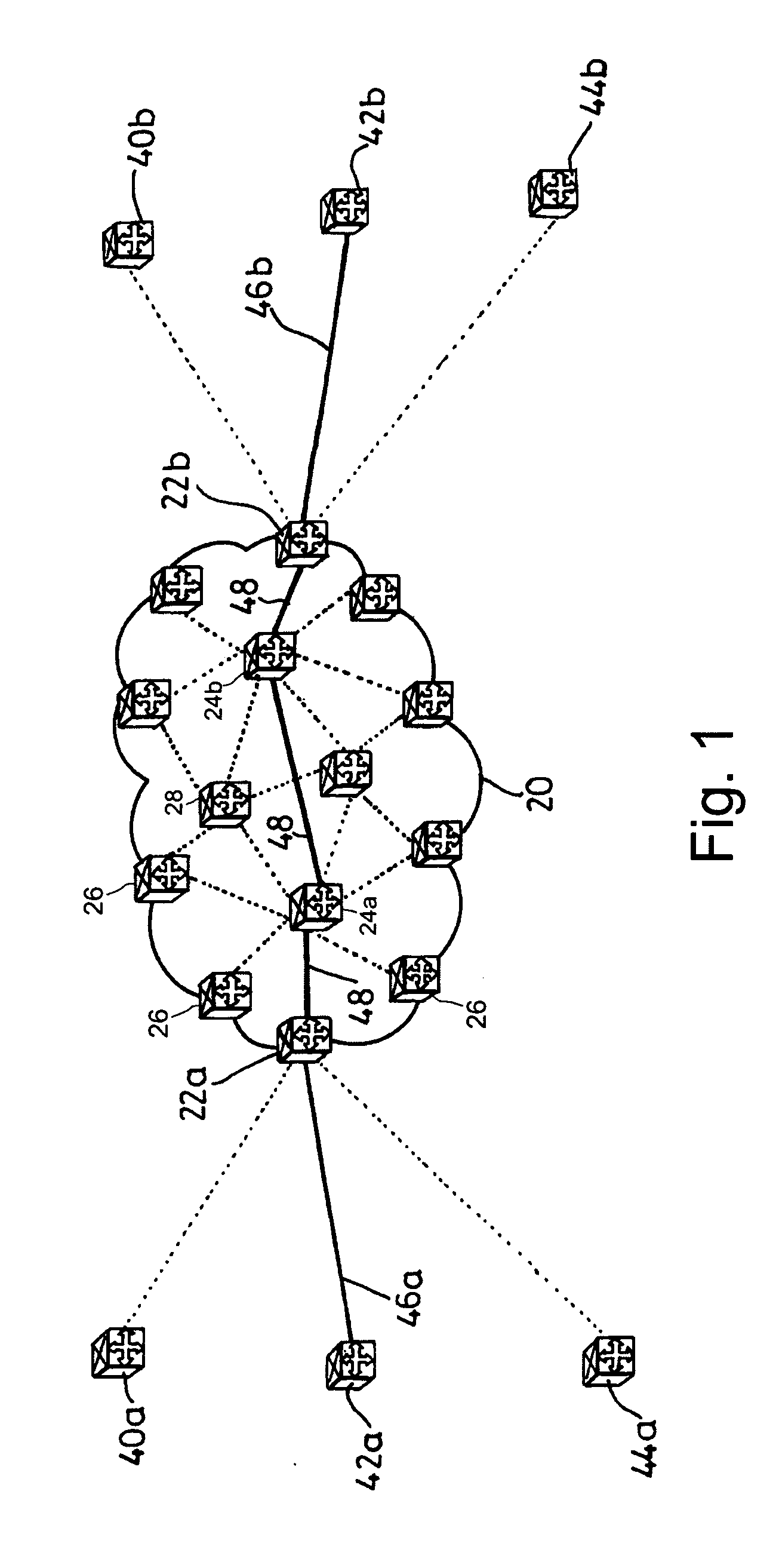
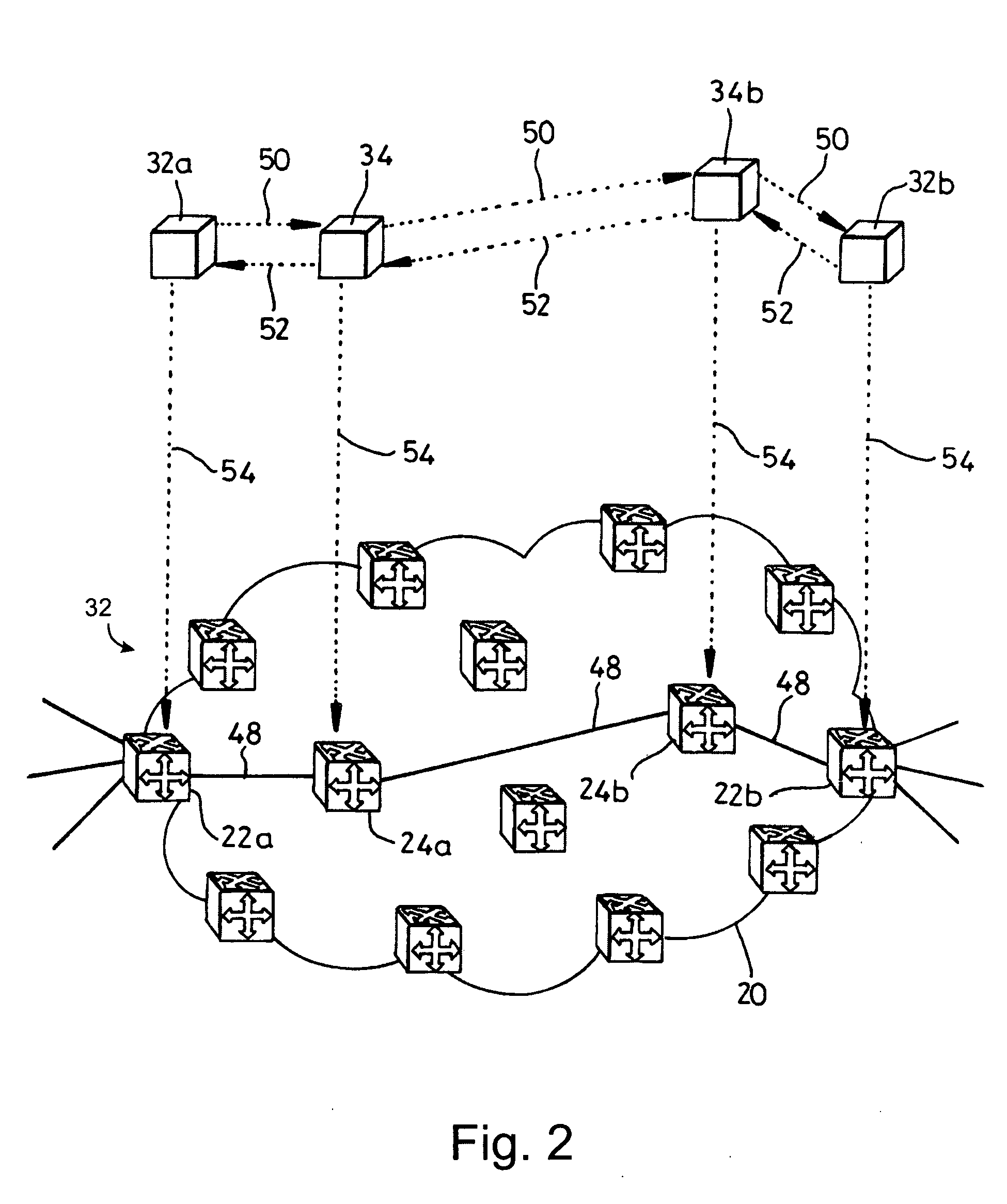
[0019]FIGS. 1 and 2 show an arrangement of Ethernet switches and communications links forming a carrier network. Carrier network cloud 20 comprises Ethernet switches 22a, 22b, 24a, 24b, 26 and 28. Ethernet switches 22a, 22b and 26 are located at the edges of carrier network 20, whereas Ethernet switches 24a, 24b, and 28 are located in the core network. Communications links (shown as straight lines) are provided between Ethernet switches 22a, 22b, 24a, 24b, 26 and 28. These communications links may be for example relatively long distance links over optical equipment such as SONET / SDH equipment with Ethernet interfaces using Generic Framing Procedure (GFP) (ITU-T Recommendation G.7041 / Y.1303). Although a carrier network is shown as an example of the type of network that the Ethernet switches can be used with, the invention is not limited to this. In addition, although core network switches 24a, 24b, and 28 are shown with a fully-meshed configuration, i.e. there is a direct communicati...
PUM
 Abstract
Description
Claims
Application Information
 - R&D
- Intellectual Property
- Life Sciences
- Materials
- Tech Scout
- Unparalleled Data Quality
- Higher Quality Content
- 60% Fewer Hallucinations
Browse by: Latest US Patents, China's latest patents, Technical Efficacy Thesaurus, Application Domain, Technology Topic, Popular Technical Reports.
© 2025 PatSnap. All rights reserved.Legal|Privacy policy|Modern Slavery Act Transparency Statement|Sitemap|About US| Contact US: help@patsnap.com


