Pitch multiplication spacers and methods of forming the same

a multi-spacer and spacer technology, applied in the field of masking techniques, can solve the problems of limiting the choice of materials, limiting the latitude of the process, and the minimum pitch of the photolithographic technique is an obstacle to the reduction of feature siz

Active Publication Date: 2007-03-01
MICRON TECH INC
View PDF98 Cites 312 Cited by
  • Summary
  • Abstract
  • Description
  • Claims
  • Application Information

AI Technical Summary

Benefits of technology

[0015] According to another aspect of the invention, a method is provided for forming an array of repeating features in an integrated circuit. The method comprises lithographically defining a plurality of resist features in a resist layer over a substrate to form a pattern. The resist features each have a width defined by lithographically. The pattern is transferred to a layer of mandrel material under the resist layer to form a plurality of mandrels on a level over the substrate. The mandrels each have a width substantially equal to a width of the resist features. A plurality of spacers is formed on the level of the mandrels without etching the mandrels after transferring the pattern. The distance between the spacers is less than the width of the mandrels. The pattern defined by the spacers is transferred to the substrate to form the array of repeating features.

Problems solved by technology

However, due to factors such as optics and light or radiation wavelength, photolithography techniques each have a minimum pitch below which a particular photolithographic technique cannot reliably form features.
Thus, the minimum pitch of a photolithographic technique is an obstacle to continued feature size reduction.
The requirement of the isotropic etch, in addition to the other requirements for compatible etches and deposited materials, can limit the choice of materials used in pitch multiplication, thereby limiting process latitude.

Method used


Image

  • Pitch multiplication spacers and methods of forming the same
  • Pitch multiplication spacers and methods of forming the same
  • Pitch multiplication spacers and methods of forming the same

Examples


Embodiment Construction

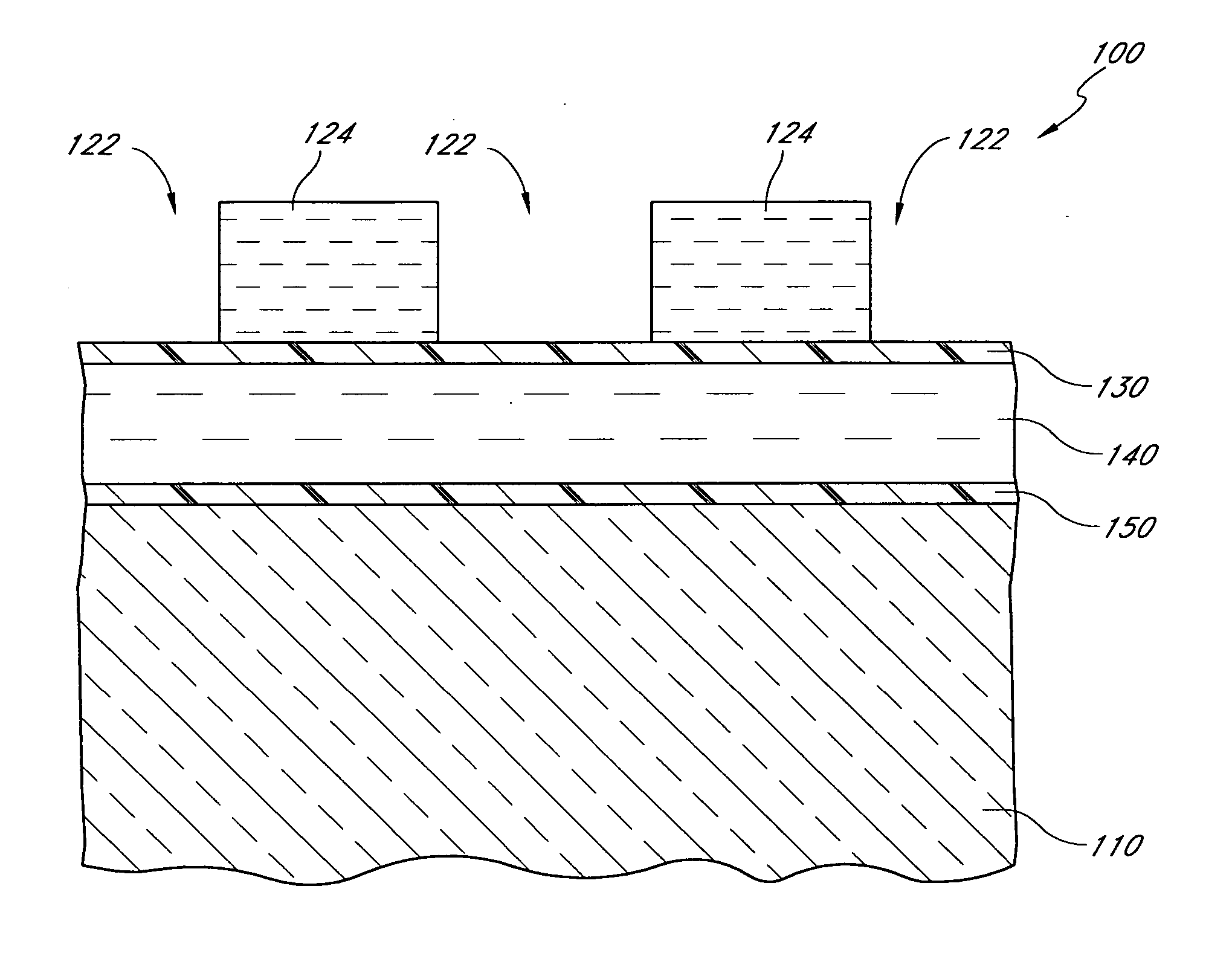
[0035] In preferred embodiments of the invention, in a masking process, mask features, such as spacers, are formed by a reaction with a temporary feature, such as a mandrel. Preferably, the spacers are formed at the sides of mandrels and a trim etch of the mandrels is not needed. The mandrels are preferably reacted with at least one other material or chemical species to form the spacers, which comprise spacer material that is a product of the reaction. A cap layer is preferably formed over the top, horizontal surface of the mandrels to inhibit reactions on that surface. Thus, the reactions preferably occur at the sides of the mandrels and convert the sidewall mandrel material into spacer material. Unreacted mandrel material is then preferably removed, to leave a pattern of free-standing spacers. Preferably, the spacers are formed without a spacer etch, i.e., without performing a directional etch that preferentially removes spacer material from horizontal surfaces. After removing the...


PUM


Abstract

Spacers in a pitch multiplication process are formed without performing a spacer etch. Rather, the mandrels are formed over a substrate and then the sides of the mandrels are reacted, e.g., in an oxidization, nitridation, or silicidation step, to form a material that can be selectively removed relative to the unreacted portions of the mandrel. The unreacted portions are selectively removed to leave a pattern of free-standing spacers. The free-standing spacers can serve as a mask for subsequent processing steps, such as etching the substrate.

Description

CROSS-REFERENCE TO RELATED APPLICATIONS [0001] This application is related to the following: U.S. patent application Ser. No. 10 / 934,778 to Abatchev et al., filed Sep. 2, 2004, entitled Method for Integrated Circuit Fabrication Using Pitch Multiplication; and U.S. Patent Provisional Application No. 60 / 662,323 to Tran et al, filed Mar. 15, 2005, entitled Pitch Reduced Patterns Relative To Photolithography Features.BACKGROUND OF THE INVENTION [0002] 1. Field of the Invention [0003] This invention relates generally to integrated circuit fabrication and more particularly, to masking techniques. [0004] 2. Description of the Related Art [0005] As a consequence of many factors, including demand for increased portability, computing power, memory capacity and energy efficiency, integrated circuits are continuously being made more dense. The sizes of the constituent features that form the integrated circuits, e.g., electrical devices and interconnect lines, are constantly being decreased to f...

Claims


Application Information

Patent Timeline
Patent Type & Authority Applications(United States)
IPC IPC(8): H01L21/302
CPCH01L21/0337H01L21/0338H01L21/32134H01L21/3088H01L21/32053H01L21/3086H01L21/31144H01L21/77H01L21/67063
Inventor SANDHU, GURTEJ S.PRALL, KIRK D.
Owner MICRON TECH INC
Why Eureka
Try Eureka