Methods and apparatuses for dynamic power control

a technology of dynamic power control and methods, applied in the field of data processing systems, can solve the problems of limiting the performance of the system, tightening the power budget of the computer system,

Active Publication Date: 2007-03-01
APPLE INC
View PDF52 Cites 56 Cited by
  • Summary
  • Abstract
  • Description
  • Claims
  • Application Information

AI Technical Summary

Benefits of technology

[0014] In one aspect of an embodiment of the present invention, a method to manage power usage in a data processing system, includes: determining information on power usage during a first time period of operation of the data processing system; and determining a performance level setting of a component of the data processing system for a second time period, which is subsequent to the first time period, using the information on the power usage during the first time period.
[0015] In one example of an embodiment, the performance level setting is determined to limit a power usage indicator under a threshold in the second time period; and the power usage indicator is a function of a history of power usage in the data processing system.
[0016] In one example of an embodiment, the data processing system includes one or more first components to be throttled in performance levels and one or more second components not to be throttled in performance levels; and the method further includes: determining an estimated power usage used by the one or more second components in the second time period. The performance level setting in the second time period is determined from the threshold, the estimated power usage used by the one or more second components, and the information on the powe

Problems solved by technology

As the operating power consumptions of the individual components of computer system creep upwards, the power budgets of the computer systems have become tighter.
It is now becoming a challenge to design a computer system to run a continuous worst-case workload while pursuing other high performance goals, such as high computing

Method used


Image

  • Methods and apparatuses for dynamic power control
  • Methods and apparatuses for dynamic power control
  • Methods and apparatuses for dynamic power control

Examples


Embodiment Construction

[0037] The following description and drawings are illustrative of the invention and are not to be construed as limiting the invention. Numerous specific details are described to provide a thorough understanding of the present invention. However, in certain instances, well known or conventional details are not described in order to avoid obscuring the description of the present invention. References to one or an embodiment in the present disclosure are not necessarily references to the same embodiment; and, such references mean at least one.

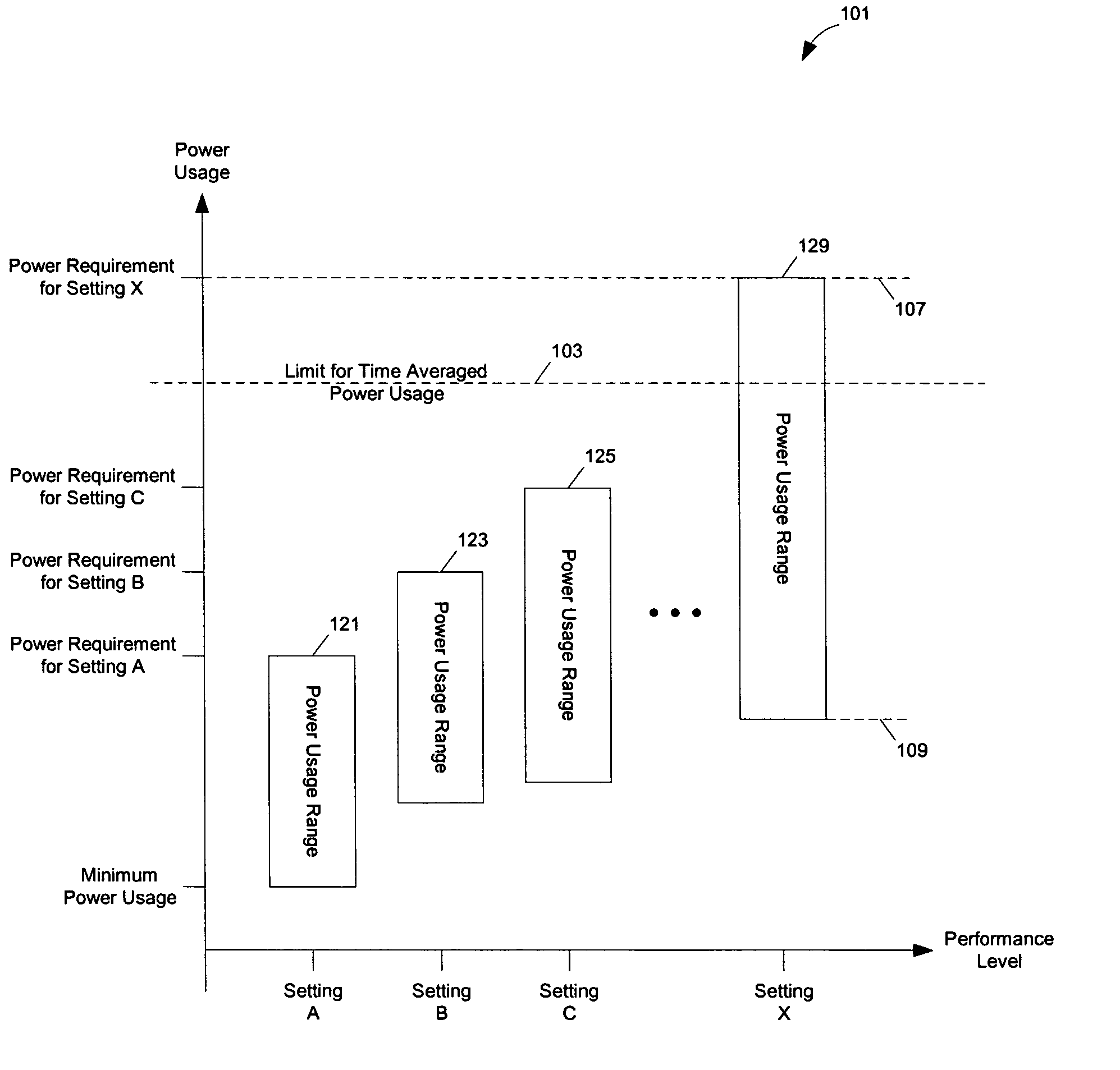
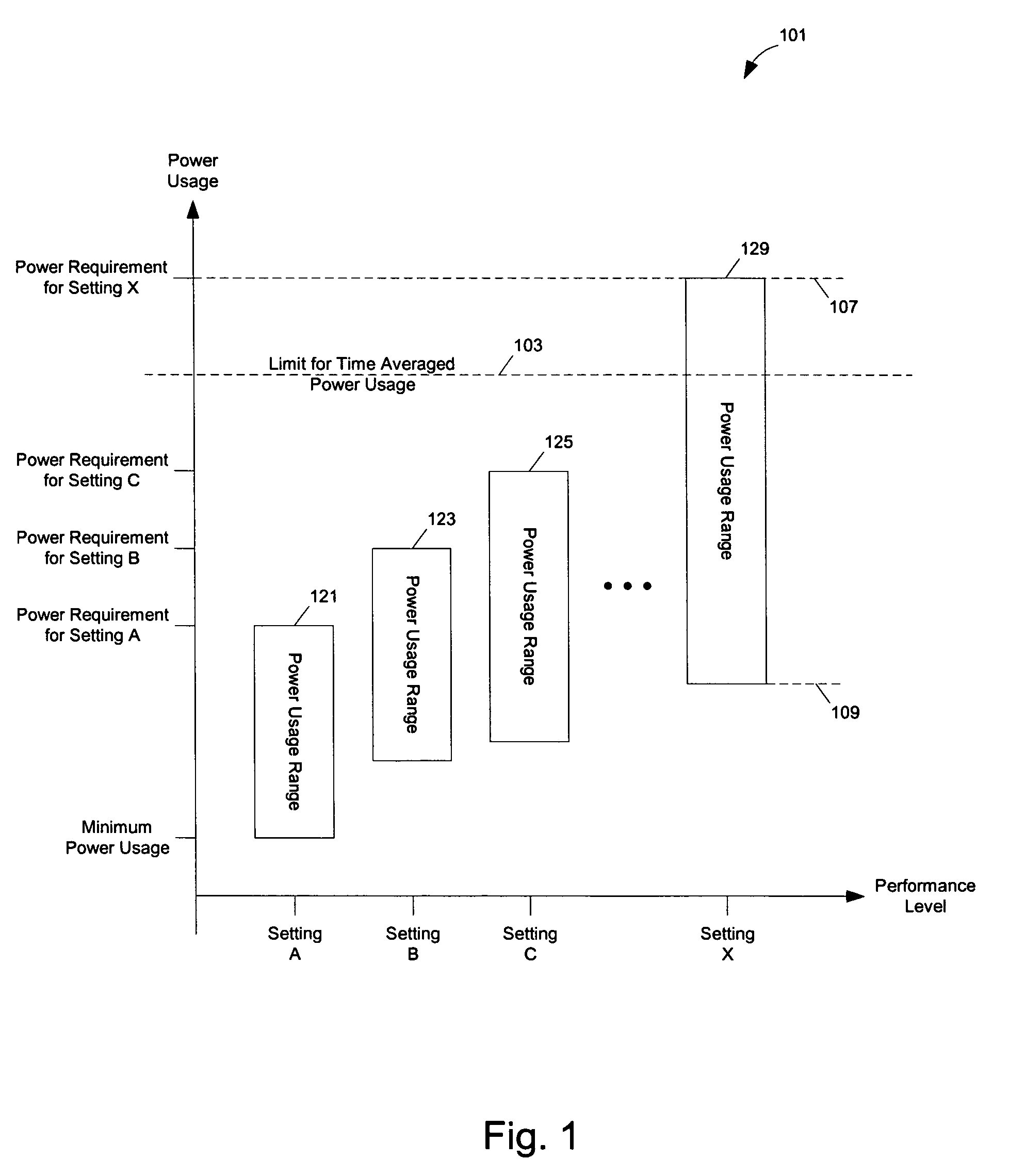
[0038] In one embodiment of the present invention, it is recognized that power consumptions in a computer system typically change frequently during typical usages. Typically, not all components are simultaneously in the maximum power consumption mode. Further, some components may not be in the maximum power consumption mode continuously for a long period of time. The power consumption of a component, such as the central processing unit (CPU) micr...


PUM


Abstract

Methods and apparatuses for dynamically budgeting power usage in a data processing system. In one aspect, a data processing system, includes: one or more first components capable of being dynamically throttled to a plurality of different performance level settings; one or more second components; and one or more power usage sensors. The one or more power usage sensors are to determine information on power usage during a first time period of operation of the data processing system. The one or more first components and the one or more second components may include a computing element to determine one of the performance level settings of the one or more first components of the data processing system for a second time period subsequent to the first time period using the information on the power usage during the first time period.

Description

TECHNOLOGY FIELD [0001] At least some embodiments of the present invention relate generally to data processing systems, and more particularly but not exclusively to the management of power usage in data processing systems. BACKGROUND [0002] Traditionally, computer systems are designed to be able to continuously run a fairly worst-case power load. Design according to such a continuous worst-case power load has never been much of a problem, because traditionally the individual components have had modest operating powers and the computer systems have had large power budgets so that the systems could sustain the load fairly naturally. [0003] As the operating power consumptions of the individual components of computer system creep upwards, the power budgets of the computer systems have become tighter. It is now becoming a challenge to design a computer system to run a continuous worst-case workload while pursuing other high performance goals, such as high computing power, compactness, qu...

Claims


Application Information

Patent Timeline
IPC IPC(8): G06F1/00
CPCY02B60/1217Y02B60/1285G06F1/3287Y02B60/1278G06F1/28G06F1/324G06F1/3296G06F1/3203G06F1/30G05D23/19G06F1/26Y02B60/1282Y02D10/00Y02B70/10Y02B70/30
Inventor CONROY, DAVID G.COX, KEITH ALANCULBERT, MICHAEL
Owner APPLE INC
Why Eureka
Try Eureka