

Shower curtain hooks
- Summary
- Abstract
- Description
- Claims
- Application Information
AI Technical Summary
Benefits of technology
Problems solved by technology
Method used
Image

Examples
Embodiment Construction
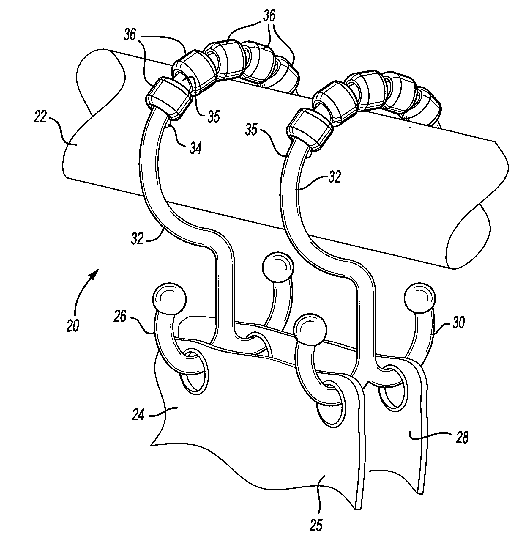
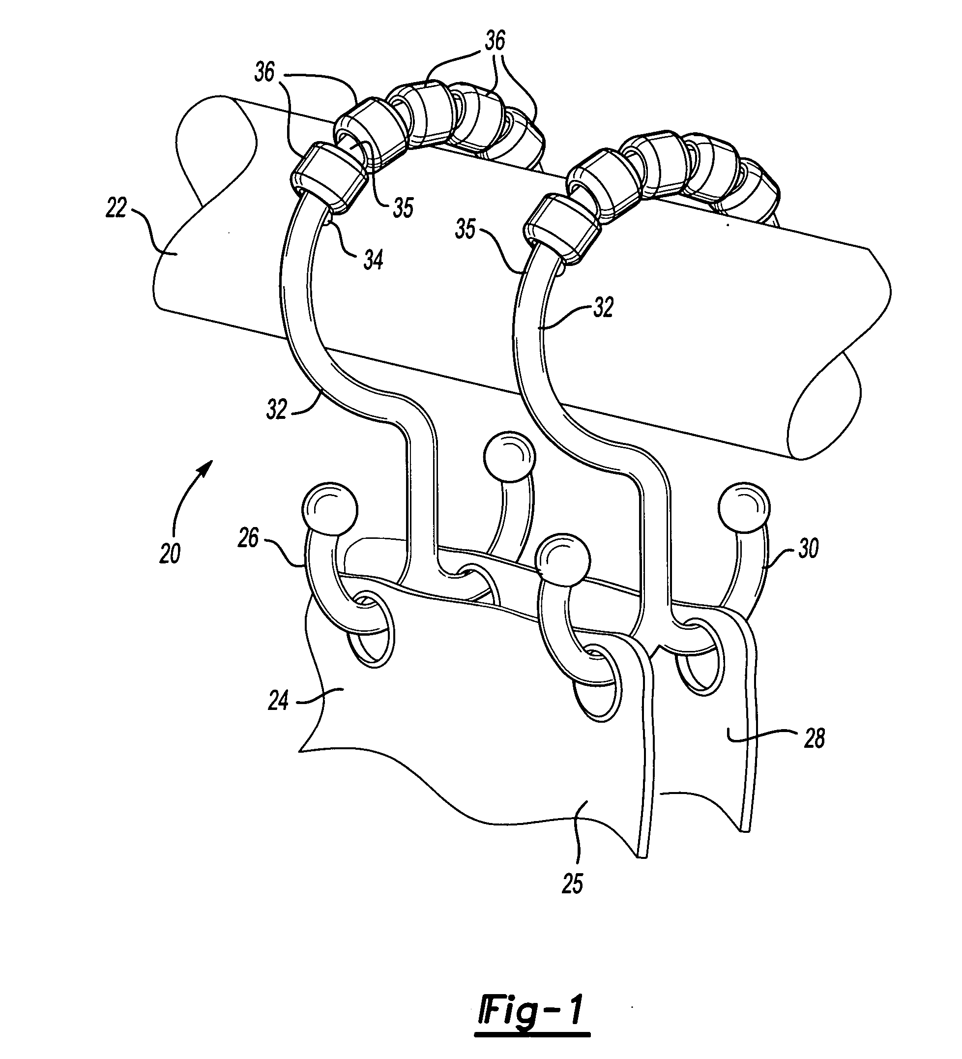
[0009] A shower environment 20 is illustrated in FIG. 1 having a curtain rod 22 with hooks 32 supporting a curtain 24 having two sheets 25 and 28. Sheet 25 is supported on a first hook portion 26 and sheet 28 is supported on a second hook portion 30 of the plurality of hooks 32. A leg portion 33 extends from the hook portions 26 and 30, and into a hoop portion 35. Stops 34 capture a plurality of rollers 36. The rollers 36 support the hooks 32 for easy sliding movement along the curtain rod 22.
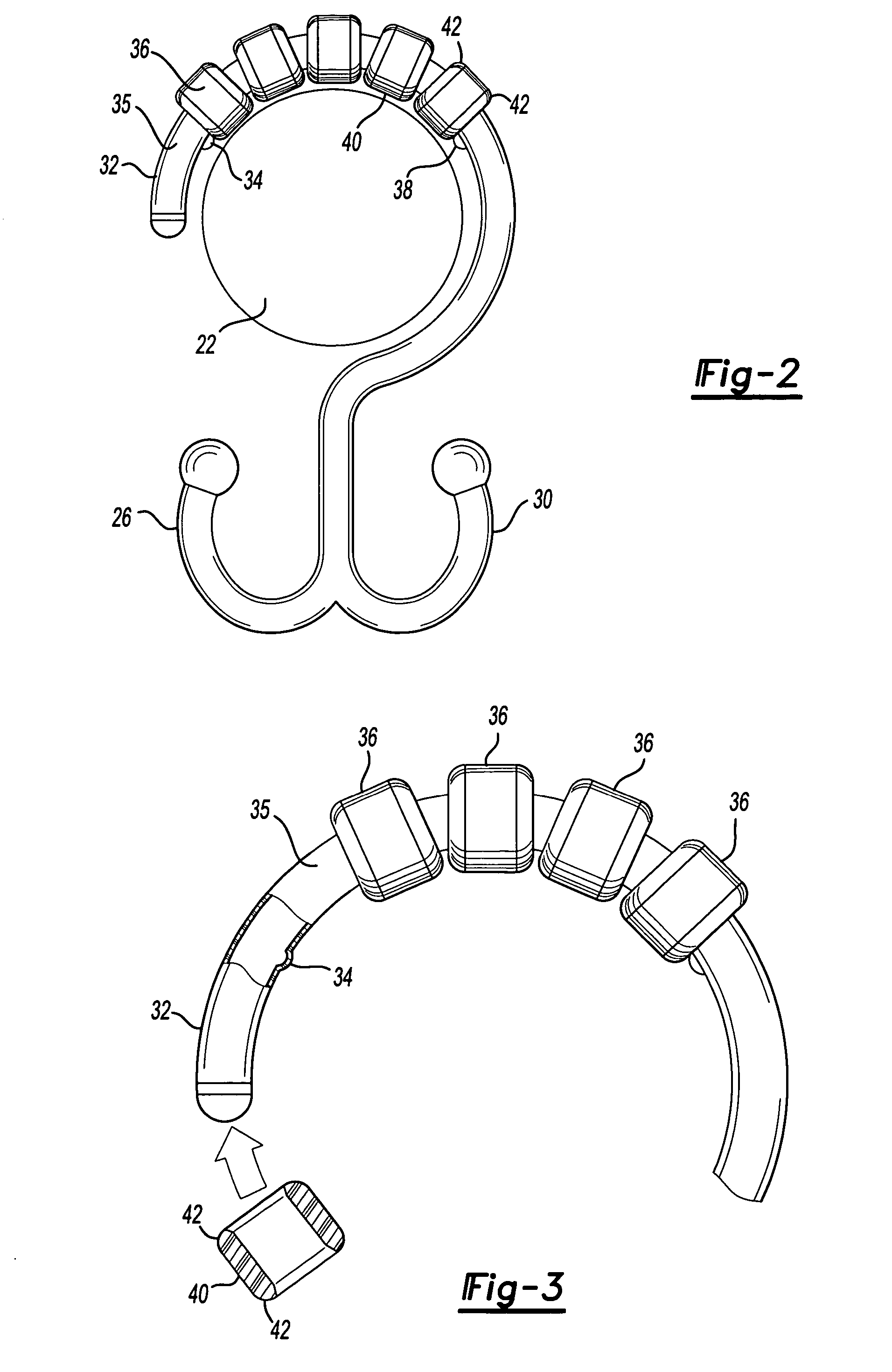
[0010] As can be appreciated from FIG. 2, stops 34 and 38 capture a plurality of rollers 36. The rollers 36 each have a generally cylindrical radially outer surface 40 at a central location, and opposed ends 42 that extend along a curve. The cylindrical outer surfaces 40 better support the hooks 32 on the curtain rod 22, when compared to the spherical prior art rollers. In addition, the use of the cylindrical outer surfaces 40 with curved ends 42 result in more space to accommodate adjacent ro...
PUM
 Abstract
Description
Claims
Application Information